FloBoss 107 Instruction Manual
6-8 Sensors and Transducers Revised June-2017
this value and stores it in the designated AI point for use by other
functions. If an update does not occur within the one-second
interval, the FB107 re-initializes the sensor. If the DVS does not
response to the re-initialization, a point fail alarm appears on the
alarm log.
6.2.1 Installing/Removing a DVS
Note: The DVS is a factory-installed option for the FB107, and
bolts onto the FB107’s exterior case. In normal operation,
you should not have to install or replace the sensor.
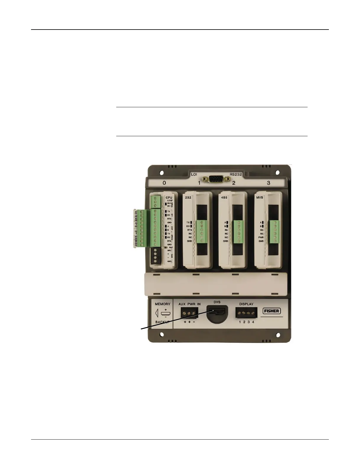
The DVS plugs into the DVS connector on the FB107 base unit
(see Figure 6-4).
Figure 6-5. FB107 Base Unit, Integral Sensor Connector
With the DVS installed, start ROCLINK 800. When the FB107
graphical interface displays, click on the DVS connector. The
graphical interface changes to reflect the installed integral DVS.

 Loading...


