Setup & Operation 13. Standard I/O Connector
VT Rev.1 95
13.1.3 Pin Assignments of Input Circuit
Input common No. 16 to 23
Remote function inside ( ) in the table above is initially assigned to input from 0 to 7.
For further details, refer to Setup & Operation 14. I/O Remote Settings.
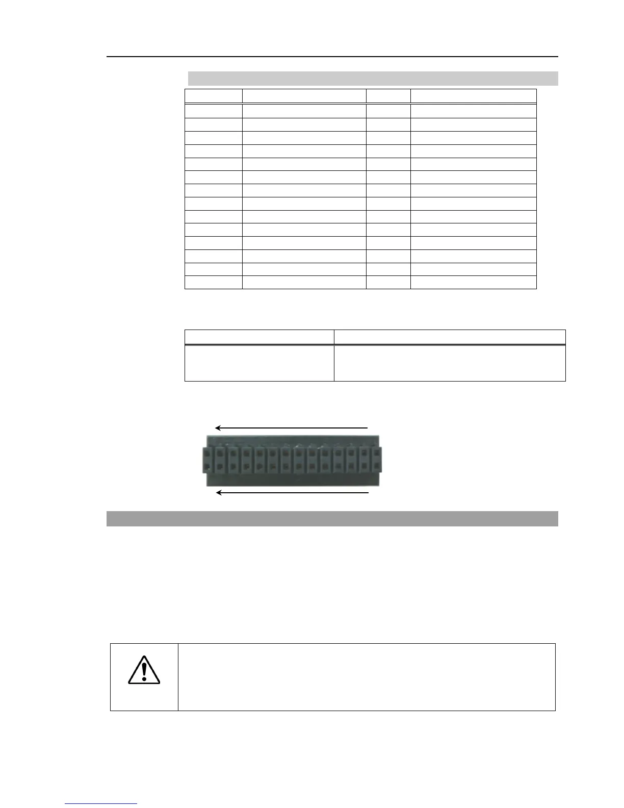
DMC 0,5/14-G1-2,54 P20THR R72 (Board side)
DFMC 0,5/14-ST-2,54 (Cable side)
* I/O connector is included with shipment.
I/O (Input) Connector pin assignment
13.2 Output Circuit
Rated Output Voltage : +12 V to +24 V ±10%
Maximum Output Current : TYP 100 mA/1 output
Output device : PhotoMOS relay
ON resistance : Less than 0.7 Ω
The following two wirings are available since non-polar PhotoMOS relay is used for
output circuit.
CAUTION
Be sure to wire the output circuit properly because it has no protection circuitry
for short-circuit and reverse-
connection. Improper wiring may cause
malfunction of the parts on the board and then improper function of the robot
 Loading...


