EasyManuals Logo
Home>Epson>Robotics>VT6L

Epson VT6L User Manual

Epson VT6L
274 pages
To Next Page IconTo Next Page
To Previous Page IconTo Previous Page
Page #113 background imageLoading...
Page #113 background image
Setup & Operation 13. Standard I/O Connector
VT Rev.1 97
13.2.3 Pin Assignments of Output Circuit
Pin No.
Signal Name
Pin No.
Signal Name
1
Output No. 0 (Ready)
10
Output No.1 (Running)
2
Output No.2 (Paused)
11
Output No.3 (Error)
3
Output No.4 (EstopOn)
12
Output No.5 (SafeguardOn)
4
Output No.6 (SError)
13
Output No.7 (Warning)
5
Output common No. 0 to 7
14
Output common No. 8 to 11
6
Output No. 8
15
Output No. 9
7
Output No.10
16
Output No.11
8
Output No. 12
17
Output No. 13
9
Output No. 14
18
Output No. 15
Remote function inside ( ) in the table above is initially assigned to output from 0 to 7.
For further details, refer to Setup & Operation 14. I/O Remote Settings.
Connector
Connector model
I/O (Output) Connector
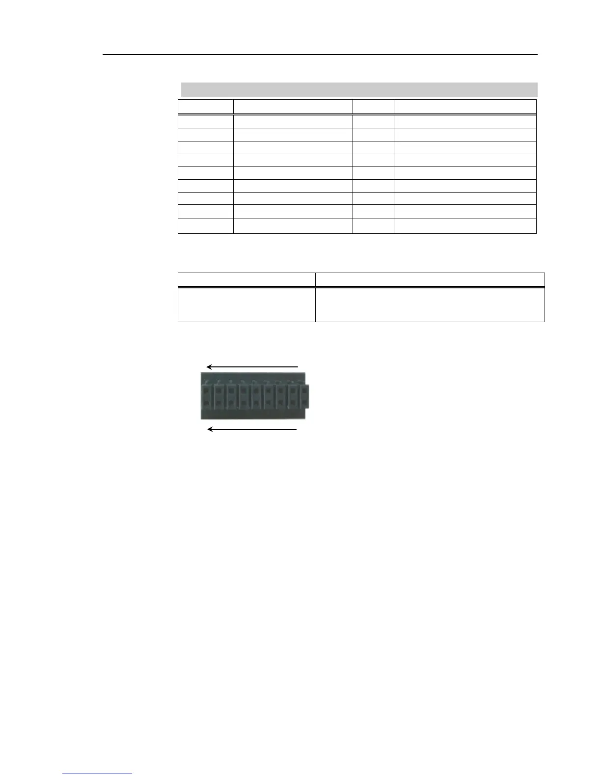
DMC 0,5/9-G1-2,54 P20THR R44 (Board side)
DFMC 0,5/ 9-ST-2,54 (Cable side)
(PHOENIX CONTACT)
* I/O connector is included with shipment.
I/O (Output) Connector pin assignment
9
1
18
10

Table of Contents

Other manuals for Epson VT6L

Questions and Answers:

Question and Answer IconNeed help?

Do you have a question about the Epson VT6L and is the answer not in the manual?

Epson VT6L Specifications

General IconGeneral
BrandEpson
ModelVT6L
CategoryRobotics
LanguageEnglish

Related product manuals