Maintenance 9. Joint #1
166 VT Rev.1
9.1 Replacing Joint #1 Motor
Name Quantity Note
Maintenance
parts
Joint #1 motor unit 1 2194596
Tools
Hexagonal
wrench
width across flats: 2.5 mm 1
For M3 hexagon socket head
cap bolts
width across flats: 3 mm 1
For M4
hexagon socket head
cap bolts
For tightening torque control
The brake is mounted on each joint to prevent the arm from lowering due to its own weight while the
controller power is OFF or the motor is OFF status. The brake does not work during replacement.
Be careful when performing maintenance work.
Turn OFF the Manipulator.
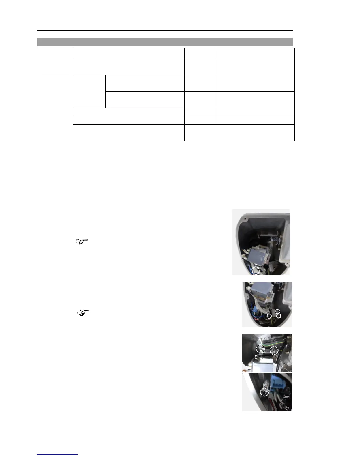
Reference: Maintenance 7.1 Arm #1 Cover.
Cut off the wire tie that binds the following cables.
Signal cable and the signal cable for AMP board
between the Joint #1 motor and the controller unit
the wire tie on the plate (Arm #1 sleeve side) and
the plate.
Hexagon socket head cap bolts: 2-M4×12 (with washer)
Be careful not to cut the harness.
the motor unit from the Arm #1.
Hexagon socket head cap bolts: 3-M4×22
(with slotted hole washer)
 Loading...


