Do you have a question about the Epson VT6L and is the answer not in the manual?
Type | 6-axis robot |
---|---|
Payload | 6 kg |
Repeatability | ±0.02 mm |
Axis | 6 |
Maximum Speed J4 | 360 °/s |
Mounting | Floor, Wall, Ceiling |
Explains the symbols used for important safety considerations in the manual.
Outlines safety precautions for personnel involved in designing and installing the robot system.
Details safety precautions for qualified operator personnel during robot system operation.
Describes the procedure and precautions for using the Emergency Stop switch.
Explains how to move robot arms when the electromagnetic brake is operating.
Provides precautions for operating the manipulator in low power status.
Details the warning labels attached to the manipulator and their meanings.
Lists the key features of the VT series controller-integrated manipulators.
Explains the structure and components of the VT series robot model number.
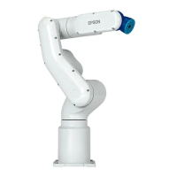
Identifies and labels the various parts of the robot manipulator.
Provides detailed dimensional drawings of the robot manipulator.
Illustrates the standard motion range of each joint of the manipulator.
Presents a typical system configuration example for VT series manipulators.
Details the technical specifications of the VT series manipulators.
Explains how to set the manipulator model within the system configuration.
Specifies the required environmental conditions for proper and safe robot system function.
Provides requirements and considerations for the base table used to anchor the manipulator.
Details the required mounting dimensions and space for installation.
Outlines procedures and safety precautions for unpacking and transporting the manipulator.
Describes the step-by-step procedure for installing the robot manipulator safely.
Details specifications and precautions for connecting the power supply to the manipulator.
Provides guidance on properly connecting various cables to the manipulator and controller.
Explains precautions for relocating and storing the manipulator.
Describes how to check and confirm the manipulator's basic orientation after installation.
Details how to attach an end effector to the robot's wrist flange.
Explains how to attach cameras and air valves to the manipulator's arms.
Covers setting load weight and inertia parameters for optimal manipulator motion.
Provides precautions for auto acceleration/deceleration settings related to manipulator posture.
Explains how to set the motion range for all joints using pulse ranges.
Describes how to physically limit the manipulator's absolute movement area using mechanical stops.
Details restrictions on manipulator operation based on combined joint angles.
Defines the manipulator's coordinate system and its origin point.
Provides instructions on how to change the manipulator model within the EPSON RC+ software.
Explains how to set the Cartesian range using XYLIM settings for operation area.
Describes the three main operation modes of the robot system: TEACH, AUTO, and TEST.
Explains how to switch between the robot system's operation modes using the teach pendant.
Details how to switch to and use the Program Mode (AUTO) for robot system operations.
Provides procedures for switching to and using the Auto Mode (AUTO) for automatic operation.
Describes the function and status indication of the LEDs on the manipulator's front panel.
Explains the function and supported USB types for the development PC connection port.
Lists precautions to be taken when connecting the development PC and the manipulator.
Details the software setup and connection check procedure for PC-to-manipulator communication.
Describes the procedure for safely disconnecting the development PC from the manipulator.
Details the camera plate unit for mounting cameras to the VT series manipulator.
Describes the tool adapter for mounting ISO flange compatible end effectors.
Explains the use of adjustable mechanical stops to limit the manipulator's motion range.
Details the external wiring kit for fixing wirings and air tubes along the manipulator.
Covers the safeguard and latch release switches connected to the EMERGENCY connector.
Explains how to connect external Emergency Stop switches to the EMERGENCY connector.
Provides the pin assignment details for the EMERGENCY connector.
Illustrates typical circuit diagrams for emergency stop and safety door connections.
Explains the function of saving manipulator data to USB memory.
Outlines precautions before using the controller status storage function.
Details the procedure for saving manipulator status to USB memory.
Lists the types of data files created by the controller status storage function.
Describes the Ethernet communication port and its purposes.
Explains how to set the IP address and subnet mask for LAN port configuration.
Provides steps to change the manipulator's IP address via the development PC connection.
Details the procedure for connecting the development PC and manipulator via Ethernet.
Describes how to disconnect the development PC from the manipulator via Ethernet.
Explains the function of the TP port for connecting the teach pendant.
Details the procedure for connecting the teach pendant to the manipulator.
Describes the input voltage range, ON/OFF voltages, and input current for the input circuit.
Details the rated output voltage, maximum output current, and wiring for the output circuit.
Explains the procedure for connecting user input/output devices via I/O cables.
Describes the functions and timings of input and output signals for remote I/O.
Provides timing diagrams for primary operations and signal sequences.
Details the schedule and points for daily, monthly, quarterly, biannual, and annual inspections.
Explains overhaul timing and the recommended replacement of parts based on operation hours.
Specifies the tightening torques for hexagon socket head cap bolts.
Describes the process of matching motor and controller origins after part replacement.
Illustrates the locations of key maintenance parts on the manipulator.
Explains how to configure recommended replacement times for parts like batteries and belts.
Details how to check and edit maintenance information using EPSON RC+.
Explains the controller backup function for storing manipulator configuration.
Lists the file names and their overview created by the 'Backup Controller' function.
Describes the procedure for backing up the manipulator status using EPSON RC+.
Explains the procedure for restoring manipulator status from saved backup data.
Describes the process of updating the manipulator's firmware.
Details the steps required to perform a firmware upgrade.
Provides procedures to recover the manipulator if it becomes inoperable.
Explains the procedure for initializing the manipulator's firmware.
Details the procedure for removing and installing the cover for Arm #1.
Details the procedure for removing and installing the cover for Arm #2.
Details the procedure for removing and installing the cover for Arm #3.
Details the procedure for removing and installing the first cover for Arm #4.
Details the procedure for removing and installing the second cover for Arm #4.
Describes the procedure for removing and installing the power cable cover.
Details the procedure for removing and installing the connector plate.
Provides instructions for replacing the cable unit of the manipulator.
Details the procedure for inserting and removing the power cable.
Step-by-step guide for replacing the motor unit of Joint #1.
States that reduction gear unit replacement is done by a serviceman.
Provides instructions for replacing the timing belt of Joint #1.
Detailed procedure for replacing the motor unit of Joint #2.
Informs that reduction gear unit replacement is handled by a serviceman.
Step-by-step guide for replacing the timing belt of Joint #2.
Provides instructions for replacing the motor unit of Joint #3.
States that reduction gear unit replacement is performed by a serviceman.
Details the procedure for replacing the timing belt of Joint #3.
Step-by-step guide for replacing the motor unit of Joint #4.
Informs that reduction gear unit replacement is handled by a serviceman.
Provides instructions for replacing the timing belt of Joint #4.
Details the procedure for replacing the motor unit of Joint #5.
States that reduction gear unit replacement is done by a serviceman.
Provides instructions for replacing the timing belt of Joint #5.
Step-by-step guide for replacing the motor unit of Joint #6.
Informs that reduction gear unit replacement is handled by a serviceman.
Details the procedure for replacing the timing belt of Joint #6.
Describes replacing the AMP board on Joints #1, #2, and #3.
Details replacing the AMP board on Joint #4.
Explains replacing the AMP board on Joints #5 and #6.
Provides the procedure for replacing the LED plate.
Details the procedure for replacing the felt sheet on Joint #2.
Explains the procedure for replacing the felt sheet on Joint #3.
Outlines the procedure for replacing the controller unit.
Details the steps for replacing the power board within the controller unit.
Provides instructions for replacing the CPU/DPB board.
Explains the procedure and precautions for replacing the lithium battery.
Details the procedure for replacing the cooling fan.
Describes the procedure for removing and installing the SD card.
Explains the purpose of calibration for matching motor encoder and controller origins.
Details the steps for performing manipulator calibration.
Describes steps for achieving more accurate positioning through calibration.
Explains how to perform accuracy testing after calibration.
Lists commands and functions that are not available for VT series manipulators.
Identifies commands that cause motion errors when using the RS-232C port.
Lists commands that cause errors during execution, categorized by function.
Details restrictions on specific functions like TP3 and loop processing.
Lists open source software programs included in the VT series manipulator product.