EasyManuals Logo
Home>Epson>Robotics>VT6L

Epson VT6L User Manual

Epson VT6L
274 pages
To Next Page IconTo Next Page
To Previous Page IconTo Previous Page
Page #252 background imageLoading...
Page #252 background image
Maintenance 18. Controller Unit
236 VT Rev.1
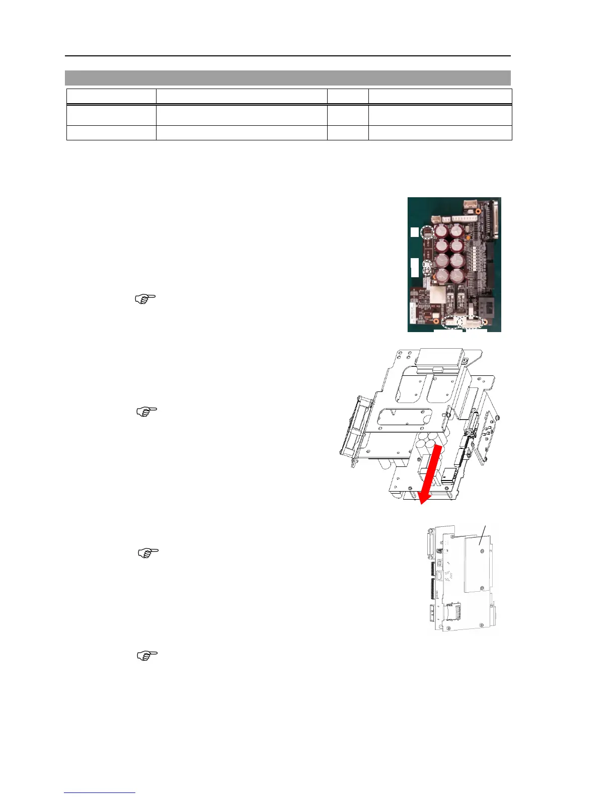
18.3 Replacing CPU/DPB Board
Name
Quantity
Note
Maintenance
parts
CPU/DPB Board 1 2193553
Tools
Cross-point screwdriver (No. 2)
1
CPU/DPB
Board
Removal
(
1)
Remove
the power board.
Reference: Maintenance 18.2 Replacing Power Board
(
2)
Disconnect
the CPU/DPB board connectors.
E: Power connector (IN/OUT ×1 for each)
F: Cooling fan connector
G: Regenerative resistor connector 1
H: Regenerative resistor connector 2
Remember the cable layout for reconnecting after
replacement.
F
G
H
E
-OUT
E-IN
(3)
Remove
the CPU/DPB board.
Binding head screws: 5-M3×6
Firstly, unscrew
the mounting screws.
Next, pull the
CPU/DPB board to the
arrow direction.
(
4)
Remove the
thermal sheet attached on the CPU board.
The
thermal sheet will be necessary again.
Be careful
not to lose them.
Be careful not to break the
thermal sheet.
Thermal sheet
(
5)
Attach
the thermal sheet on the surface (the side with no
connectors) of
the new CPU/DPB board
Make sure not to attach
the sheet on the wrong surface.
NOTE
NOTE
NOTE
NOTE

Table of Contents

Other manuals for Epson VT6L

Questions and Answers:

Question and Answer IconNeed help?

Do you have a question about the Epson VT6L and is the answer not in the manual?

Epson VT6L Specifications

General IconGeneral
BrandEpson
ModelVT6L
CategoryRobotics
LanguageEnglish

Related product manuals