03-7
Auxiliary Systems
03-7
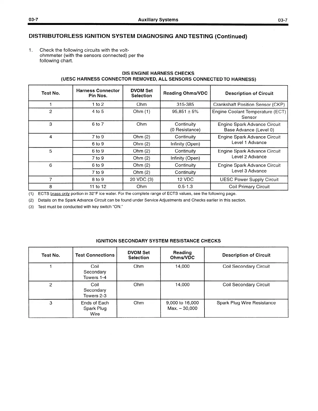
DISTRIBUTORLESS IGNITION SYSTEM DIAGNOSING ANDTESTING (Continued)
1.
Check the following circuits with the volt-
ohmmeter (with the sensors connected) per the
following chart.
DIS ENGINE HARNESS CHECKS
(UESC HARNESS CONNECTOR REMOVED, ALL SENSORS CONNECTED TO HARNESS)
Test No.
Harness Connector
Pin Nos.
DVOM Set
Selection
Reading Ohms/VDC
Description of Circuit
/
1 1 to2 Ohm 315-385
I Crankshaft Position Sensor (CKP) 1
2 4 to 5 Ohm (1) 95,851 + 5%
Engine Coolant Temperature (ECT)
Sensor
3
4
6 to 7 Ohm Continuity Engine Spark Advance Circuit
(0 Resistance)
Base Advance (Level 0)
7 to 9 Ohm (2) Continuity Engine Spark Advance Circuit
6 to 9 Ohm (2) Infinity (Open) Level 1 Advance
5 6 to 9 Ohm (2) Continuity Engine Spark Advance Circuit
7 to 9 Ohm (2) Infinity (Open) Level 2 Advance
6 6 to 9 Ohm (2) Continuity Engine Spark Advance Circuit
7 to 9 Ohm (2) Continuity Level 3 Advance
7 8 to 9 20 VDC (3) 12 VDC UESC Power Supply Circuit
8 11 to 12 Ohm 0.5-I .3 Coil Primary Circuit
(1.) ECTS brass only portion in 32°F ice water. For the complete range of ECTS values, see the following page.
(2) Details on the Spark Advance Circuit can be found under Service Adjustments and Checks earlier in this section.
(3) Test must be conducted with key switch “ON.”
IGNITION SECONDARY SYSTEM RESISTANCE CHECKS
Test No.
Test Connections
1
2
3
DVOM Set Reading
Selection Ohms/VDC
Description of Circuit
Coil
Secondary
Towers 1-4
Ohm
14,000
Coil Secondary Circuit
Coil
Secondary
Towers 2-3
Ohm 14,000 Coil Secondary Circuit
Ends of Each
Spark Plug
Wire
Ohm 9,000 to 16,000 Spark Plug Wire Resistance
Max. - 30,000
 Loading...


