02-61 Engine Service, 2.3L
02-61
DISASSEMBLY AND ASSEMBLY (Continued)
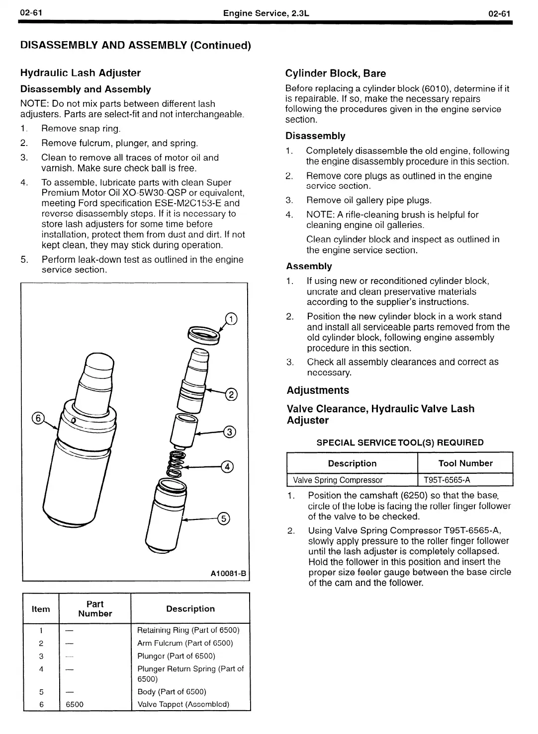
Hydraulic Lash Adjuster
Disassembly and Assembly
NOTE: Do not mix parts between different lash
adjusters. Parts are select-fit and not interchangeable.
1.
Remove snap ring.
2.
Remove fulcrum, plunger, and spring.
3. Clean to remove all traces of motor oil and
varnish. Make sure check ball is free.
4. To assemble, lubricate parts with clean Super
Premium Motor Oil X0-5W30-QSP or equivalent,
meeting Ford specification ESE-M2CI 53-E and
reverse disassembly steps. If it is necessary to
store lash adjusters for some time before
installation, protect them from dust and dirt. If not
kept clean, they may stick during operation.
5.
Perform leak-down test as outlined in the engine
service section.
Cylinder Block, Bare
Before replacing a cylinder block (6010), determine if it
is repairable. If so, make the necessary repairs
following the procedures given in the engine service
section.
Disassembly
1. Completely disassemble the old engine, following
the engine disassembly procedure in this section.
2. Remove core plugs as outlined in the engine
service section.
3.
Remove oil gallery pipe plugs.
4. NOTE: A rifle-cleaning brush is helpful for
cleaning engine oil galleries.
Clean cylinder block and inspect as outlined in
the engine service section.
Assembly
1.
If using new or reconditioned cylinder block,
uncrate and clean preservative materials
according to the supplier’s instructions.
2.
Position the new cylinder block in a work stand
and install all serviceable parts removed from the
old cylinder block, following engine assembly
procedure in this section.
Al0081-E
Item
Part
Number
Description
5
6
6500
2. Using Valve Spring Compressor T95T-6565-A,
slowly apply pressure to the roller finger follower
until the lash adjuster is completely collapsed.
Hold the follower in this position and insert the
proper size feeler gauge between the base circle
of the cam and the follower.
Retaining Ring (Part of 6500)
Arm Fulcrum (Part of 6500)
Plunger (Part of 6500)
Plunger Return Spring (Part of
6500)
Body (Part of 6500)
Valve Tappet (Assembled)
3.
Check all assembly clearances and correct as
necessary.
Adjustments
Valve Clearance, Hydraulic Valve Lash
Adjuster
SPECIAL SERVICE TOOL(S) REQUIRED
.
Description
Tool Number
Valve Spring Compressor
T95T-6565-A
1.
Position the camshaft (6250) so that the base,
circle of the lobe is facing the roller finger follower
of the valve to be checked.
 Loading...


