03-75
Auxiliary Systems
03-75
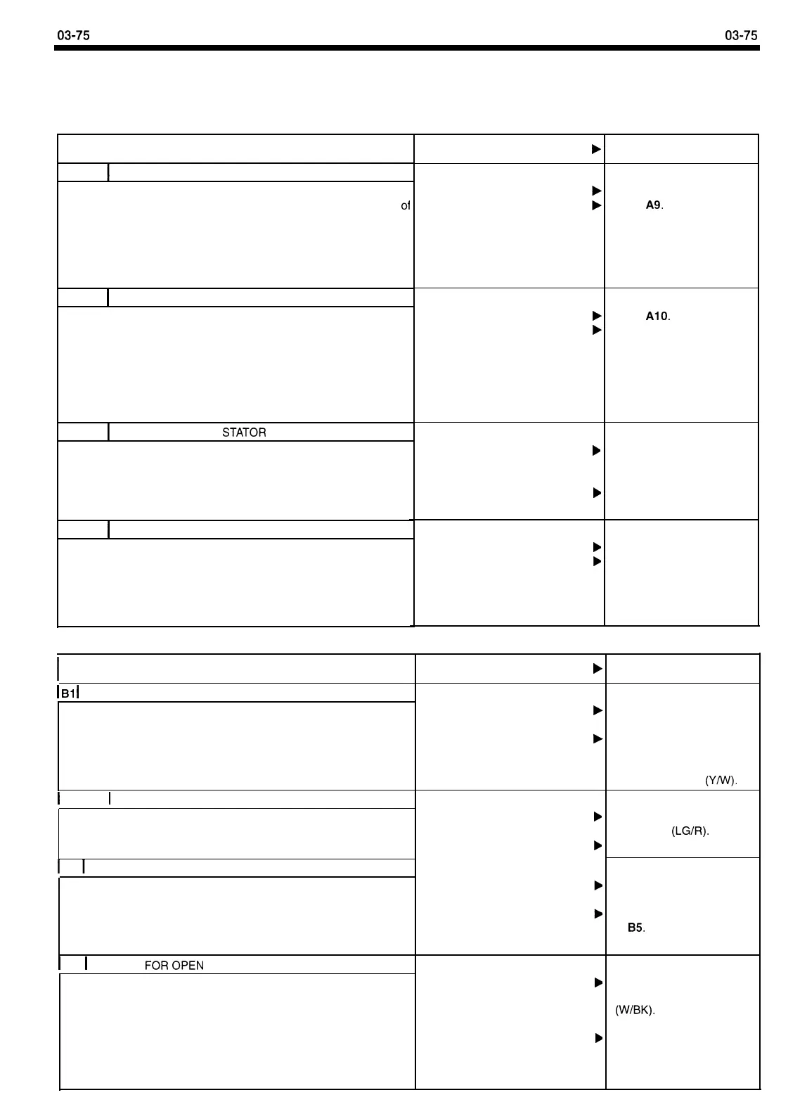
GENERATOR DIAGNOSIS AND TESTING (Continued)
PINPOINTTEST A: DEAD BATTERY/NO GENERATOR OUTPUT (Continued)
ACTION TO TAKE
TEST STEP RESULT
b
A8
CHECK FOR SHORTED RECTIFIER
l
Remove one-pin S connector from generator.
l
Measure voltage between the S terminal on the back
01
the generator and ground.
l
Measure voltage between the positive (+) battery
terminal and the S terminal on the back of the
generator.
l
Is either voltage reading greater than 1 volt?
A9
1
CHECK VOLTAGE DROP IN B+ CIRCUIT
l
Install S connector.
l
Start engine.
l
Turn on headlights or any accessory.
l
With engine running at 2000 RPM, measure voltage
drop between the B+ terminal on the back of the
generator and the positive (+) battery post.
l
Is voltage drop less than 0.5 volt?
Yes
No
Yes
No
b
b
A10
CHECK FOR OPEN
STATOR
PHASE
l
Connect test point F on the voltage regulator to the
negative (-) battery post using a jumper wire.
l
Repeat Generator Output Test.
l
Is generator output greater than the minimum
output specified?
Yes
b
No
b
All
1
CHECK FOR OPEN/SHORTED FIELD
l
Remove generator.
l
Remove voltage regulator.
l
Measure resistance between the generator slip rings.
l
Is resistance greater than 10 ohms OR less than 1
ohm?
Yes
No
b
b
REPLACE generator.
GO to A9.
GO to
AlO.
REPAIR excess voltage drop
in Circuits 38, 290, and
37.
CHECK fuse link in Circuits
38,290, and 37 and the
connections between the
battery and under-hood fuse
box.
REPLACE voltage regulator
REPLACE generator.
REPLACE generator.
CHECK for worn brushes
(less than 8mm long) or
open brush leads and
REPLACE if required. If OK,
REPLACE voltage regulator
PINPOINTTEST B: INDICATOR LAMP ON, ENGINE RUNNING
I
TEST STEP
RESULT
b
ACTION TO TAKE
1
Bl
1
CHECK FOR OPENACIRCUIT
Yes
No
GO to B2.
l
Measure voltage at test point A on the voltage
regulator.
l
Is voltage at test point A equal to battery voltage?
CHECK fuse or fuse link in
Circuit 36 and REPLACE if
required. If OK, REPAIR
open in Circuit 36
(Y/w).
1
B2
1
CHECK FOR SHORTED I CIRCUIT
Yes
No
REPAIR short to ground in
Circuit 904
(LG/R).
GO to B3.
l
Remove three-pin voltage regulator connector.
l
Turn key to ON position.
l
Is indicator lamp on?
1
B3
1
CHECK S CIRCUIT FUNCTION
Yes
No
REMOVE jumper wire. GO
to B4.
REMOVE jumper wire. GO
to
B5.
l
Install voltage regulator connector.
l
Remove one-pin S connector.
l
Connect wiring harness S terminal, Circuit 4 (W/BK) to
the positive (+) battery post using a jumper wire.
l
Is indicator lamp on?
1
B4
1
CHECK FOROPEN S CIRCUIT
Yes
b
No
b
REPAIR open or excess
resistance in Circuit 4
(W/BK).
l
Remove three-pin voltage regulator connector.
l
Measure wiring resistance between the one-pin S
connector and the S (center) pin of the voltage
regulator connector.
l
Is resistance greater than 1 ohm?
CHECK for loose or bent pin
in voltage regulator or
connector. If OK, REPLACE
voltage regulator.
 Loading...


