02-I 4
Engine Service, 2.3L
02-I 4
2.3L ENGINE SERVICE (Continued)
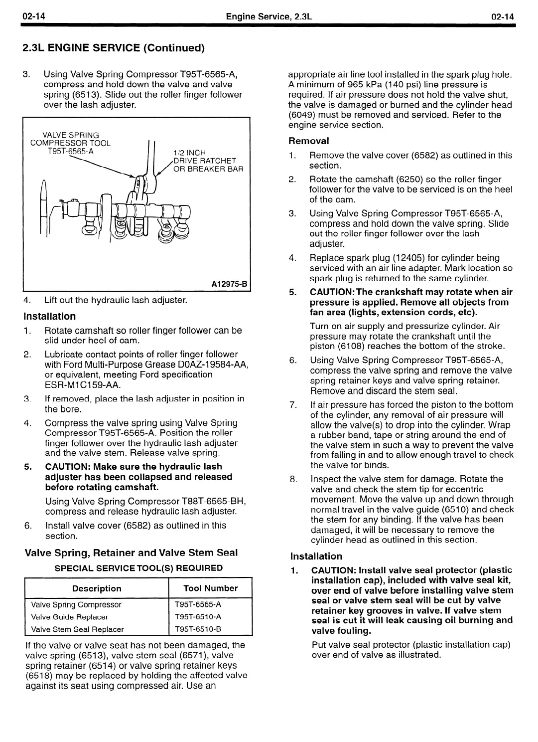
3.
Using Valve Spring Compressor T95T-6565-A,
compress and hold down the valve and valve
spring (6513). Slide out the roller finger follower
over the lash adjuster.
VALVE SPRING
COMPRESSOR TOOL
I I
T95T-6565-A
l/2 INCH
DRIVE RATCHET
OR BREAKER BAR
Al 2975-B
4.
Lift out the hydraulic lash adjuster.
Installation
1.
Rotate camshaft so roller finger follower can be
slid under heel of cam.
2.
Lubricate contact points of roller finger follower
with Ford Multi-Purpose Grease DOAZ-19584-AA,
or equivalent, meeting Ford specification
ESR-Ml Cl 599AA.
3.
If removed, place the lash adjuster in position in
the bore.
4.
Compress the valve spring using Valve Spring
Compressor T95T-6565-A. Position the roller
finger follower over the hydraulic lash adjuster
and the valve stem. Release valve spring.
5.
CAUTION:
Make sure the hydraulic lash
adjuster has been collapsed and released
before rotating camshaft.
Using Valve Spring Compressor T88T-6565-BH,
compress and release hydraulic lash adjuster.
6.
Install valve cover (6582) as outlined in this
section.
Valve Spring, Retainer and Valve Stem Seal
SPECIAL SERVICE TOOL(S) REQUIRED
Description
I
Tool Number
Valve Spring Compressor
Valve Guide Replacer
Valve Stem Seal Replacer
T95T-6565-A
T95T-651 O-A
T95T-651 O-B
If the valve or valve seat has not been damaged, the
valve spring (6513), valve stem seal (6571), valve
spring retainer (6514) or valve spring retainer keys
(6518) may be replaced by holding the affected valve
against its seat using compressed air. Use an
appropriate air line tool installed in the spark plug hole.
A minimum of 965 kPa (140 psi) line pressure is
required. If air pressure does not hold the valve shut,
the valve is damaged or burned and the cylinder head
(6049) must be removed and serviced. Refer to the
engine service section.
Removal
1.
2.
3.
4.
5.
6.
7.
8.
Remove the valve cover (6582) as outlined in this
section.
Rotate the camshaft (6250) so the roller finger
follower for the valve to be serviced is on the heel
of the cam.
Using Valve Spring Compressor T95T-6565-A,
compress and hold down the valve spring. Slide
out the roller finger follower over the lash
adjuster.
Replace spark plug (12405) for cylinder being
serviced with an air line adapter. Mark location so
spark plug is returned to the same cylinder.
CAUTION:The crankshaft may rotate when air
pressure is applied. Remove all objects from
fan area (lights, extension cords, etc).
Turn on air supply and pressurize cylinder. Air
pressure may rotate the crankshaft until the
piston (6108) reaches the bottom of the stroke.
Using Valve Spring Compressor T95T-6565-A,
compress the valve spring and remove the valve
spring retainer keys and valve spring retainer.
Remove and discard the stem seal.
If air pressure has forced the piston to the bottom
of the cylinder, any removal of air pressure will
allow the valve(s) to drop into the cylinder. Wrap
a rubber band, tape or string around the end of
the valve stem in such a way to prevent the valve
from falling in and to allow enough travel to check
the valve for binds.
Inspect the valve stem for damage. Rotate the
valve and check the stem tip for eccentric
movement. Move the valve up and down through
normal travel in the valve guide (6510) and check
the stem for any binding. If the valve has been
damaged, it will be necessary to remove the
cylinder head as outlined in this section.
Installation
1.
CAUTION: Install valve seal protector (plastic
installation cap), included with valve seal kit,
over end of valve before installing valve stem
seal or valve stem seal will be cut by valve
retainer key grooves in valve. If valve stem
seal is cut it will leak causing oil burning and
valve fouling.
Put valve seal protector (plastic installation cap)
over end of valve as illustrated.
 Loading...


