01-25
Engine Service
01-25
SERVICE PROCEDURES (Continued)
Camshaft Bearing Journals
1.
Measure each journal twice, 90 degrees apart, to
determine journal wear, size, and out-of-round.
2. Check measurements against specifications in
the specification section.
3. If journals are excessively out-of-round or worn,
regrind to a standard undersize. Refer to Master
Parts Catalogue. If journals are too worn to be
refinished to an available undersize, replace
camshaft.
Camshaft Journals Oil Clearance
1.
Measure camshaft bearings and camshaft
bearing journals as outlined in this section.
2. Subtract size of journal from the size of its
bearing.
3.
Check clearance against specifications in
specification section.
4.
If clearance is excessive, but camshaft journals
are within specifications, simply install new
bearings. If both bearings and journals are worn,
turn camshaft journals to a standard undersize
and install new undersize bearings.
Camshaft Runout
1.
NOTE: Check camshaft journals for out-of-round
before checking for runout, or an out-of-round
condition on the center journal could be confused
for an excess runout condition. Set suitable
V-blocks on surface plate. Support outer
camshaft journals on V-blocks.
2.
Set up TOOL-4201-C, or equivalent, Dial
Indicator with Bracketry to check center bearing
journal.
3.
Zero dial indicator.
4.
Slowly rotate camshaft to determine overall
runout. If runout exceeds 0.03mm (0.0012 in.),
replace camshaft.
n
DIAL
INDICATOR
Al 4453-B
Cam Lobe Lift (Camshaft Removed)
There are two ways of measuring cam lobe lift with the
camshaft bearing (6261) removed: with a vernier
caliper camshaft bearing or on a lathe or cam grinder
with a dial indicator. The second method is more
accurate.
With Calipers
1.
Inspect camshaft bearing as outlined in this
section.
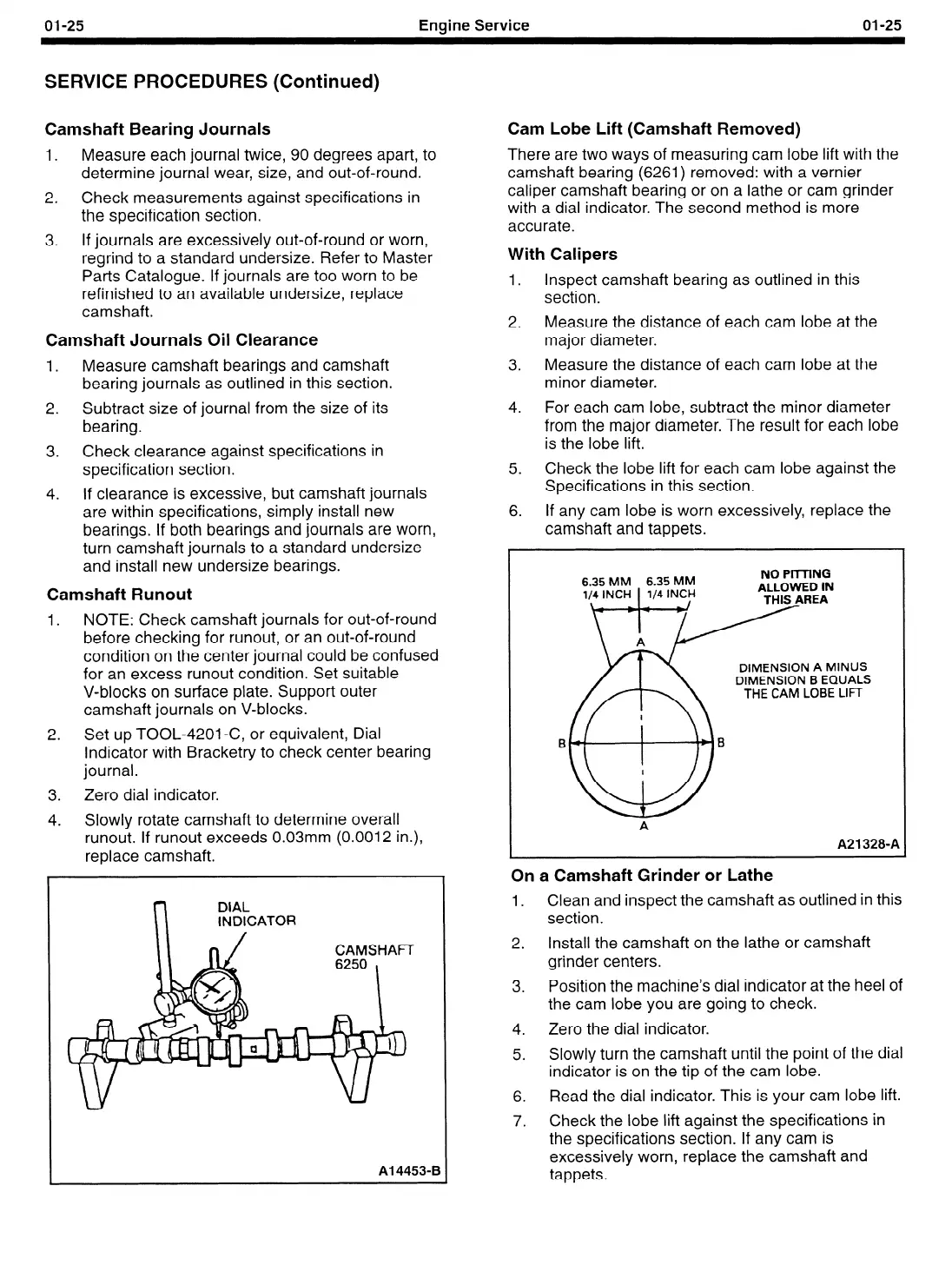
2.
Measure the distance of each cam lobe at the
major diameter.
3.
Measure the distance of each cam lobe at the
minor diameter.
4.
For each cam lobe, subtract the minor diameter
from the major diameter. The result for each lobe
is the lobe lift.
5.
Check the lobe lift for each cam lobe against the
Specifications in this section.
6.
If any cam lobe is worn excessively, replace the
camshaft and tappets.
6.35 MM 6.35 MM
NO Pi-lTlNG
li”CHff4 lN;zf
DIMENSION A MINUS
DIMENSION B EQUALS
THE CAM LOBE LIFT
A
A21 328-A
On a Camshaft Grinder or Lathe
1. Clean and inspect the camshaft as outlined in this
section.
2.
Install the camshaft on the lathe or camshaft
grinder centers.
3.
Position the machine’s dial indicator at the heel of
the cam lobe you are going to check.
4.
Zero the dial indicator.
5.
Slowly turn the camshaft until the point of the dial
indicator is on the tip of the cam lobe.
6.
Read the dial indicator. This is your cam lobe lift.
7.
Check the lobe lift against the specifications in
the specifications section. If any cam is
excessively worn, replace the camshaft and
tappets.
 Loading...


