02-62 Engine Service, 2.3L
02-62
DISASSEMBLY AND ASSEMBLY (Continued)
CC
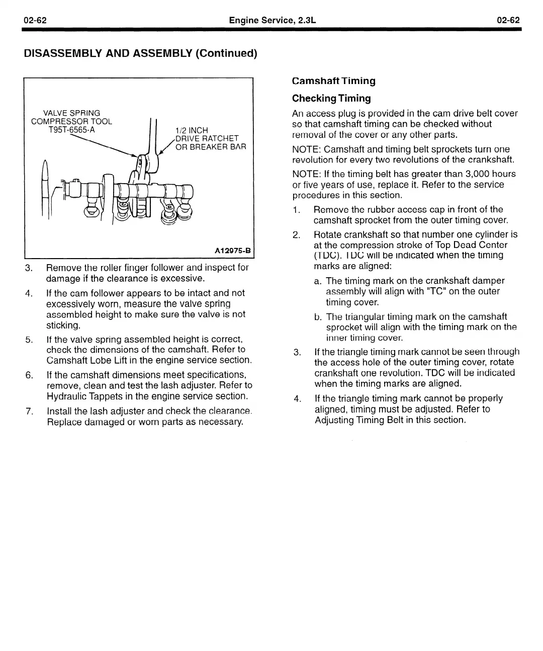
VALVE SPRING
IMPRESSOR TOOL
T95T-6565-A
II
l/2 INCH
RAT
‘CHET
;EAK ER BAR
Al 2975-B
3. Remove the roller finger
follower and inspect
damage if the clearance
is excessive.
for
4. If the cam follower appears to be intact and not
excessively worn, measure the valve spring
assembled height to make sure the valve is not
sticking.
5. If the valve spring assembled height is correct,
check the dimensions of the camshaft. Refer to
Camshaft Lobe Lift in the engine service section.
6. If the camshaft dimensions meet specifications,
remove, clean and test the lash adjuster. Refer to
Hydraulic Tappets in the engine service section.
7. Install the lash adjuster and check the clearance.
Replace damaged or worn parts as necessary.
Camshaft Timing
Checking Timing
An access plug is provided in the cam drive belt cover
so that camshaft timing can be checked without
removal of the cover or any other parts.
NOTE: Camshaft and timing belt sprockets turn one
revolution for every two revolutions of the crankshaft.
NOTE: If the timing belt has greater than 3,000 hours
or five years of use, replace it. Refer to the service
procedures in this section.
1.
2.
Remove the rubber access cap in front of the
camshaft sprocket from the outer timing cover.
Rotate crankshaft so that number one cylinder is
at the compression stroke of Top Dead Center
(TDC). TDC will be indicated when the timing
marks are aligned:
a. The timing mark on the crankshaft damper
assembly will align with “TC” on the outer
timing cover.
b. The triangular timing mark on the camshaft
sprocket will align with the timing mark on the
inner timing cover.
If the triangle timing mark cannot be seen through
the access hole of the outer timing cover, rotate
crankshaft one revolution. TDC will be indicated
when the timing marks are aligned.
If the triangle timing mark cannot be properly
aligned, timing must be adjusted. Refer to
Adjusting Timing Belt in this section.
 Loading...


