01-15
Engine Service
0145
SERVICE PROCEDURES (Continued)
Crankshaft End Play
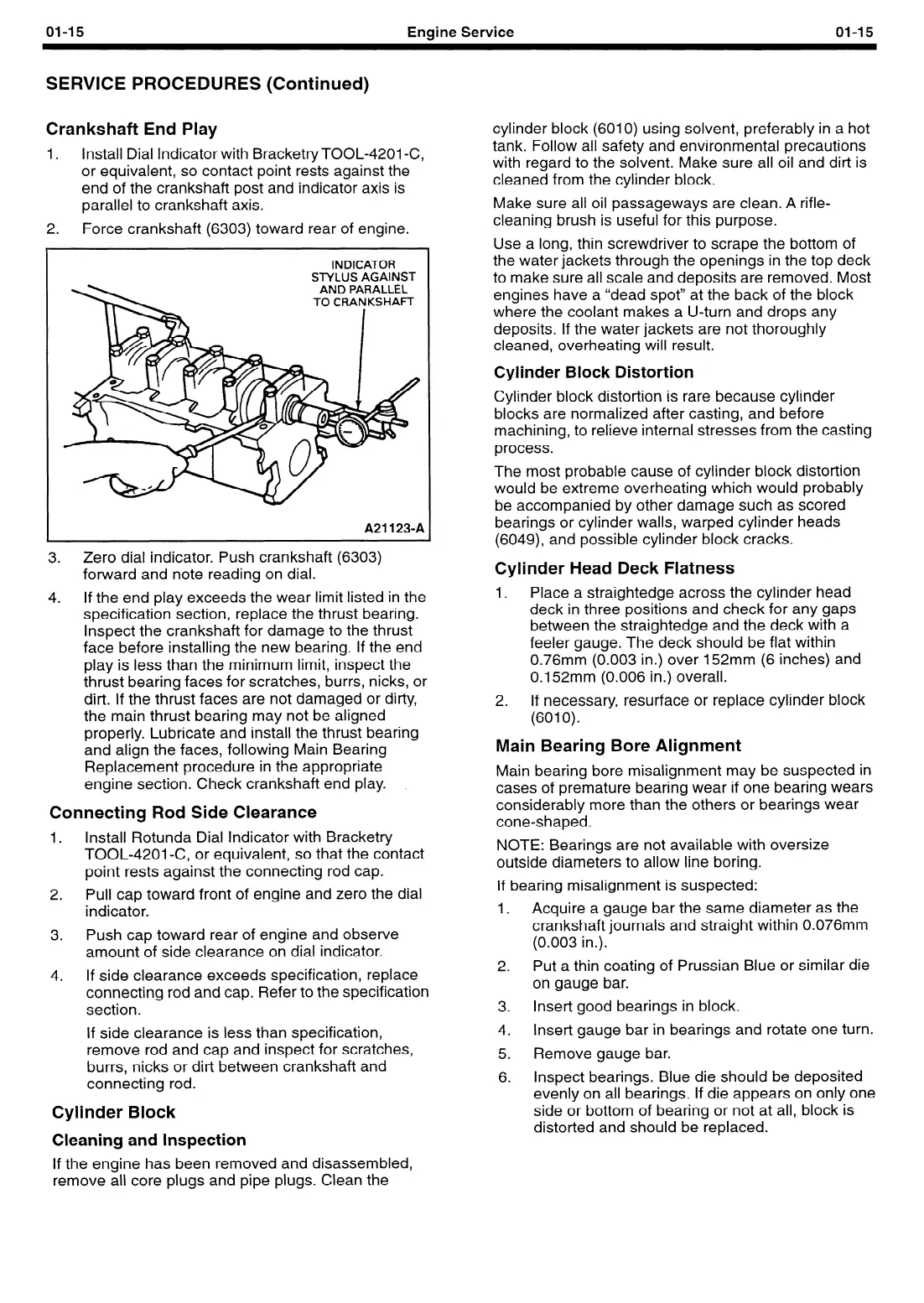
1.
Install Dial Indicator with Bracketry TOOL-4201 -C,
or equivalent, so contact point rests against the
end of the crankshaft post and indicator axis is
parallel to crankshaft axis.
2. Force crankshaft (6303) toward rear of engine.
INDICATOR
STYLUS AGAINST
AND PARALLEL
A211234
3.
Zero dial indicator. Push crankshaft (6303)
forward and note reading on dial.
4. If the end play exceeds the wear limit listed in the
specification section, replace the thrust bearing.
Inspect the crankshaft for damage to the thrust
face before installing the new bearing. If the end
play is less than the minimum limit, inspect the
thrust bearing faces for scratches, burrs, nicks, or
dirt. If the thrust faces are not damaged or dirty,
the main thrust bearing may not be aligned
properly. Lubricate and install the thrust bearing
and align the faces, following Main Bearing
Replacement procedure in the appropriate
engine section. Check crankshaft end play.
.
Connecting Rod Side Clearance
1.
Install Rotunda Dial Indicator with Bracketry
TOOL-4201-C, or equivalent, so that the contact
point rests against the connecting rod cap.
2.
Pull cap toward front of engine and zero the dial
indicator.
3. Push cap toward rear of engine and observe
amount of side clearance on dial indicator.
4. If side clearance exceeds specification, replace
connecting rod and cap. Refer to the specification
section.
If side clearance is less than specification,
remove rod and cap and inspect for scratches,
burrs, nicks or dirt between crankshaft and
connecting rod.
Cylinder Block
Cleaning and Inspection
If the engine has been removed and disassembled,
remove all core plugs and pipe plugs. Clean the
cylinder block (6010) using solvent, preferably in a hot
tank. Follow all safety and environmental precautions
with regard to the solvent. Make sure all oil and dirt is
cleaned from the cylinder block.
Make sure all oil passageways are clean. A rifle-
cleaning brush is useful for this purpose.
Use a long, thin screwdriver to scrape the bottom of
the water jackets through the openings in the top deck
to make sure all scale and deposits are removed. Most
engines have a “dead spot” at the back of the block
where the coolant makes a U-turn and drops any
deposits. If the water jackets are not thoroughly
cleaned, overheating will result.
Cylinder Block Distortion
Cylinder block distortion is rare because cylinder
blocks are normalized after casting, and before
machining, to relieve internal stresses from the casting
process.
The most probable cause of cylinder block distortion
would be extreme overheating which would probably
be accompanied by other damage such as scored
bearings or cylinder walls, warped cylinder heads
(6049) and possible cylinder block cracks.
Cylinder Head Deck Flatness
1.
Place a straightedge across the cylinder head
deck in three positions and check for any gaps
between the straightedge and the deck with a
feeler gauge. The deck should be flat within
0.76mm (0.003 in.) over 152mm (6 inches) and
0.152mm (0.006 in.) overall.
2.
If necessary, resurface or replace cylinder block
(6010).
Main Bearing Bore Alignment
Main bearing bore misalignment may be suspected in
cases of premature bearing wear if one bearing wears
considerably more than the others or bearings wear
cone-shaped.
NOTE: Bearings are not available with oversize
outside diameters to allow line boring.
If bearing misalignment is suspected:
1.
Acquire a gauge bar the same diameter as the
crankshaft journals and straight within 0.076mm
(0.003 in.).
2.
Put a thin coating of Prussian Blue or similar die
on gauge bar.
3.
Insert good bearings in block.
4.
Insert gauge bar in bearings and rotate one turn.
5.
Remove gauge bar.
6.
Inspect bearings. Blue die should be deposited
evenly on all bearings. If die appears on only one
side or bottom of bearing or not at all, block is
distorted and should be replaced.
 Loading...


