03-6 Auxiliary Systems
03-6
DISTRIBUTORLESS IGNITION SYSTEM DIAGNOSING AND TESTING
Diagnosis Equipment
To accurately diagnose DIS, certain diagnostic
equipment and tools are required. In addition, the
suggested diagnostic equipment may make the job
easier and more convenient.
Prior to diagnosing DIS, obtain the following test
equipment or equivalent:
l
Spark tester, neon bulb type (Champion CT-436)
There is no need to disconnect a plug wire; just
place this spark tester on a spark plug wire to
determine if spark is being provided to the plug.
This is especially useful for those hard-to-reach
plug wires.
l
Spark tester, gap type (special service tool
081 P-6666-A)
Connect this gap type spark tester between any
spark plug wire and engine ground to instantly
determine if spark is being provided to the plug. A
spark plug with a broken side electrode is not
sufficient to check for spark and may lead to
incorrect results.
l
Volt-ohmmeter (Rotunda 014-00575)
A volt-ohmmeter is essential for gathering system
operating data during diagnosis, testing, and
engine servicing procedures. This digital volt-
ohmmeter (DVOM) can also be used for general
purpose electrical troubleshooting on conventional
starting and charging systems.
l
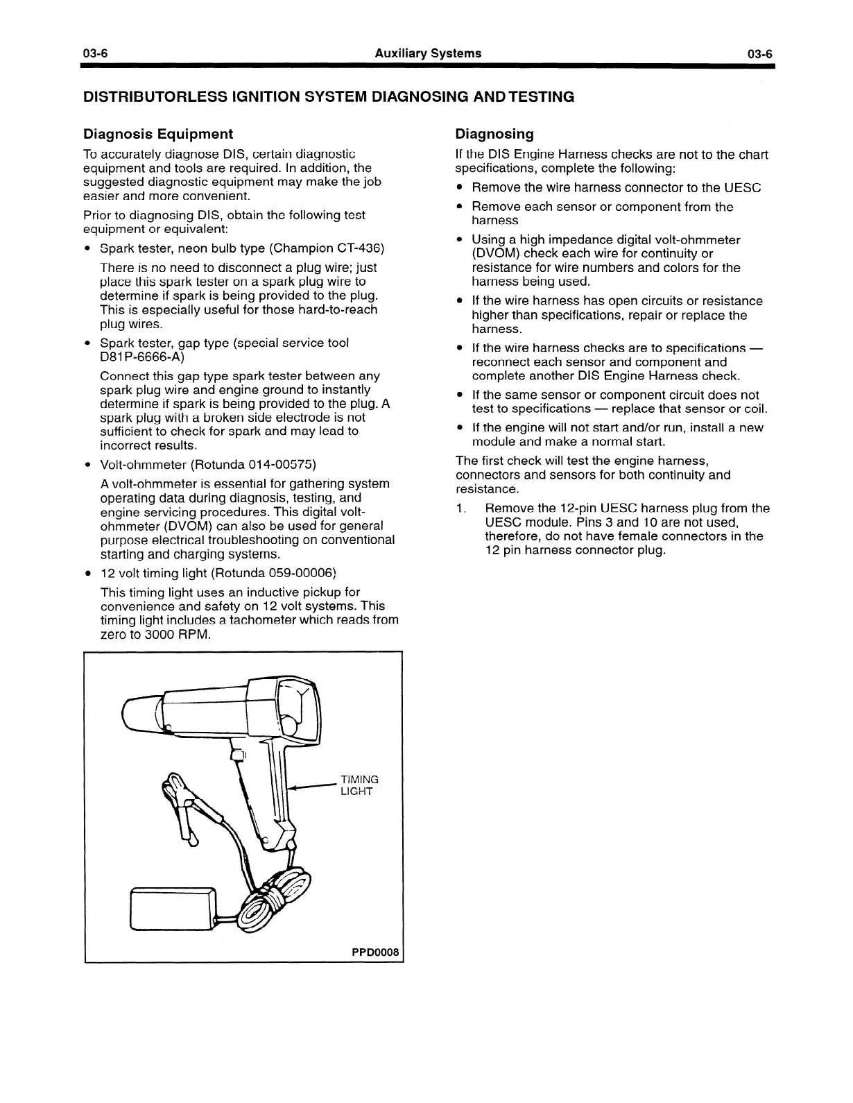
12 volt timing light (Rotunda 059-00006)
This timing light uses an inductive pickup for
convenience and safety on 12 volt systems. This
timing light includes a tachometer which reads from
zero to 3000 RPM.
Diagnosing
If the DIS Engine Harness checks are not to the chart
specifications, complete the following:
l
Remove the wire harness connector to the UESC
l
Remove each sensor or component from the
harness
l
Using a high impedance digital volt-ohmmeter
(DVOM) check each wire for continuity or
resistance for wire numbers and colors for the
harness being used.
l
If the wire harness has open circuitsor resistance
higher than specifications, repair or replace the
harness.
l
If the wire harness checks are to specifications -
reconnect each sensor and component and
complete another DIS Engine Harness check.
l
If the same sensor or component circuit does not
test to specifications - replace that sensor or coil.
l
If the engine will not start and/or run, install a new
module and make a normal start.
The first check will test the engine harness,
connectors and sensors for both continuity and
resistance.
1.
Remove the 12,pin UESC harness plug from the
UESC module. Pins 3 and 10 are not used,
therefore, do not have female connectors in the
12 pin harness connector plug.
TIMING
LIGHT
 Loading...


