03-15
Auxiliary Systems
03-l 5
DISTRIBUTORLESS IGNITION SYSTEM REMOVAL AND INSTALLATION (Continued)
Installation
1.
Install the ignition coil (12029) and the four
ignition coil pack retaining screws on the
generator mounting bracket (10153).
2. Tighten the four ignition coil retaining screws to
4.5-7.0 Nom (36-63 lb-in).
3. Connect the engine wiring harness (12A200)
electrical connector to the ignition coil (12029).
4.
To connect the spark plug wire set (12259) on the
ignition coil in their proper locations, squeeze the
locking tabs on the coil retainer and push
downward on the boot with a slight side-to-side
twist. Each of the terminals is identified on the
ignition coil (12029). The firing order of the coil is
1-3-4-2. Check that each of the spark plug wires
is fully seated and both locking tabs are engaged.
Ignition Wires
SPECIAL SERVICE TOOL(S) REQUIRED
Description
Tool Number
Spark Plug Wire Remover
T74P-6666-A
Removal
1. Remove spark plug wires from spark plugs with
\
Spark Plug Wire Remover T74P-6666-A, pulling
outward on the boot with a slight side-to-side
twist. Do not pull on the spark plug wire set
(12259).
SPARK PLUG
WIRE REMOVER
T74P-6666-A
TWIST AND PULL
B3496-E
2. Squeeze the locking tabs on the coil retainer and
pull upward on the boot with a slight side-to-side
twist to disconnect the spark plug wire set
(12259) from the ignition coil. Do not pull on the
spark plug wire set (12259).
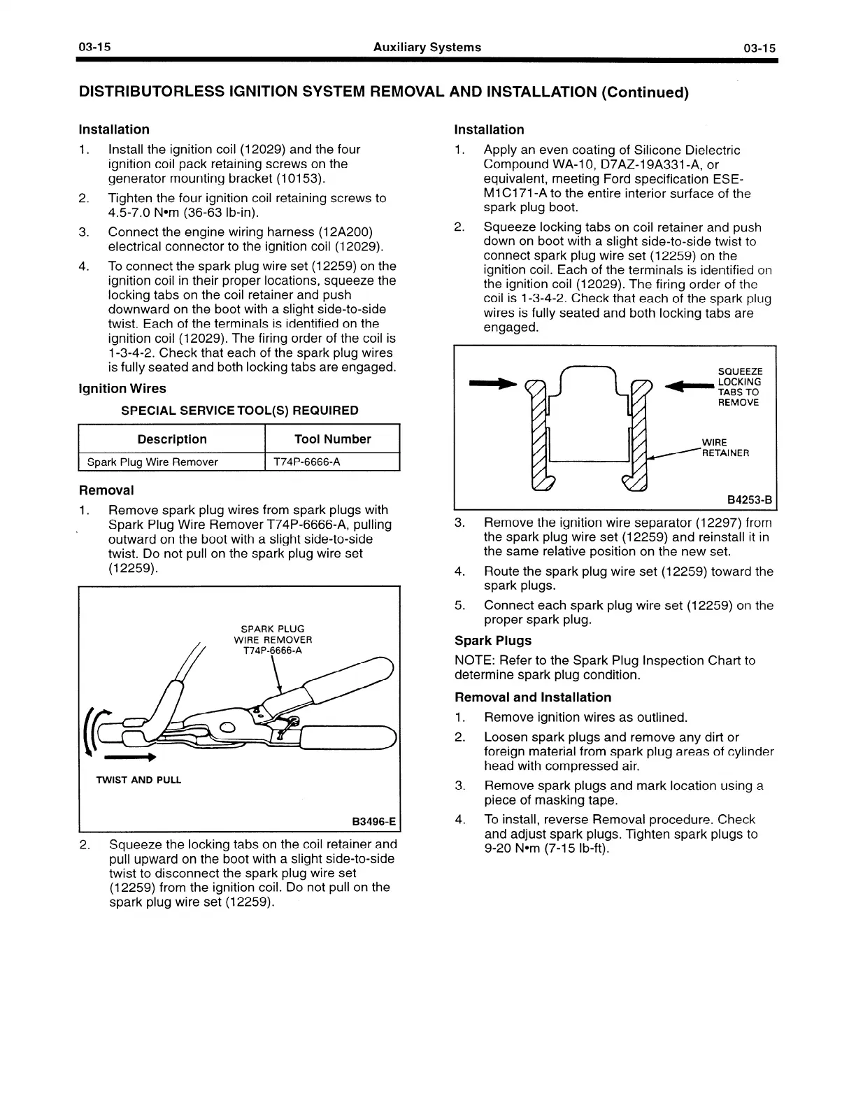
Installation
1.
Apply an even coating of Silicone Dielectric
Compound WA-1 0, D7AZ-19A331 -A, or
equivalent, meeting Ford specification ESE-
Ml Cl 71 -A to the entire interior surface of the
spark plug boot.
2.
Squeeze locking tabs on coil retainer and push
down on boot with a slight side-to-side twist to
connect spark plug wire set (12259) on the
ignition coil. Each of the terminals is identified on
the ignition coil (12029). The firing order of the
coil is 1-3-4-2. Check that each of the spark plug
wires is fully seated and both locking tabs are
engaged.
SQUEEZE
- gs”‘T”oG
-
REMOVE
WIRE
RETAINER
B4253-B
3. Remove the ignition wire separator (12297) from
the spark plug wire set (12259) and reinstall it in
the same relative position on the new set.
4. Route the spark plug wire set (12259) toward the
spark plugs.
5. Connect each spark plug wire set (12259) on the
proper spark plug.
Spark Plugs
NOTE: Refer to the Spark Plug Inspection Chart to
determine spark plug condition.
Removal and Installation
1. Remove ignition wires as outlined.
2. Loosen spark plugs and remove any dirt or
foreign material from spark plug areas of cylinder
head with compressed air.
3. Remove spark plugs and mark location using a
piece of masking tape.
4. To install, reverse Removal procedure. Check
and adjust spark plugs. Tighten spark plugs to
9-20 Nom (7-15 lb-ft).
 Loading...


