02-51
Engine Service, 2.3L
02-51
2.3L ENGINE SERVICE (Continued)
Item
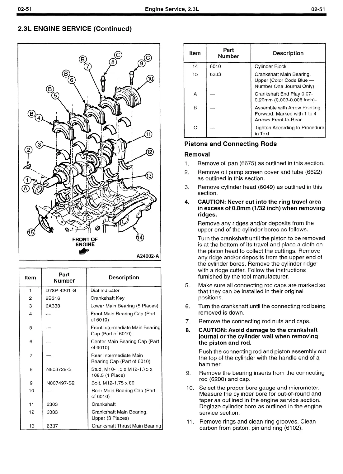
1 *
2
3
4
D78P-4201 -G
6B316
6A338
5
6
-
7
8
N803729-S
9
10
11
12
13
N80749722
6303
6333
6337
Part
Number
Description
Dial Indicator
Crankshaft Key
Lower Main Bearing (5 Places)
Front Main Bearing Cap (Part
of 6010)
Front Intermediate Main BearinS
Cap (Part of 6010)
Center Main Bearing Cap (Part
of 6010)
Rear Intermediate Main
Bearing Cap (Part of 6010)
Stud, MIO-1.5 x M12-1.75 x
108.5 (1 Place)
Bolt, M12-1.75 x 80
Rear Main Bearing Cap (Part
of 6010)
Crankshaft
Crankshaft Main Bearing,
Upper (3 Places)
Crankshaft Thrust Main Beariq
Item
Part
Number
Description
14
6010
Cylinder Block
15 6333
Crankshaft Main Bearing,
Upper (Color Code Blue -
Number One Journal Only)
A -
Crankshaft End Play 0.07-
0.2Omm (0.003-0.008 Inch) q
B -
Assemble with Arrow Pointing
Forward. Marked with 1 to 4
Arrows Front-to-Rear
c -
Tighten According to Procedure
in Text
Pistons and Connecting Rods
1.
2.
3.
4.
5.
6.
7.
8.
9.
10.
11.
Removal
Remove oil pan (6675) as outlined in this section.
Remove oil pump screen cover and tube (6622)
as outlined in this section.
Remove cylinder head (6049) as outlined in this
section.
CAUTION: Never cut into the ring travel area
in excess of 0.8mm (l/32 inch) when removing
ridges.
Remove any ridges and/or deposits from the
upper end of the cylinder bores as follows.
Turn the crankshaft until the piston to be removed
is at the bottom of its travel and place a cloth on
the piston head to collect the cuttings. Remove
any ridge and/or deposits from the upper end of
the cylinder bores. Remove the cylinder ridge4
with a ridge cutter. Follow the instructions
furnished by the tool manufacturer.
Make sure all connecting rod caps are marked so
that they can be installed in their original
positions.
Turn the crankshaft until the connecting rod being
removed is down.
Remove the connecting rod nuts and caps.
CAUTION: Avoid damage to the crankshaft
journal or the cylinder wall when removing
the piston and rod.
Push the connecting rod and piston assembly out
the top of the cylinder with the handle end of a
hammer.
Remove the bearing inserts from the connecting
rod (6200) and cap.
Select the proper bore gauge and micrometer.
Measure the cylinder bore for out-of-round and
taper as outlined in the engine service section.
Deglaze cylinder bore as outlined in the engine
service section.
Remove rings and clean ring grooves. Clean
carbon from piston, pin and ring (6102).
 Loading...


