03-46
Auxiliary Systems
03-46
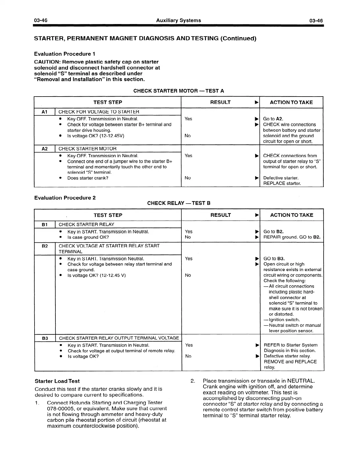
STARTER, PERMANENT MAGNET DIAGNOSIS AND TESTING (Continued)
Evaluation Procedure 1
CAUTION: Remove plastic safety cap on starter
solenoid and disconnect hardshell connector at
solenoid “S” terminal as described under
“Removal and Installation” in this section.
CHECK STARTER MOTOR -TEST A
TEST STEP
RESULT
b
Al 1 CHECK FOR VOLTAGE TO STARTER
l
Key OFF. Transmission in Neutral.
l
Check for voltage between starter B+ terminal and
starter drive housing.
l
Is voltage OK? (12-12.45V)
Yes
No
A2 1 CHECK STARTER MOTOR
I
l
Key OFF. Transmission in Neutral.
l
Connect one end of a jumper wire to the starter B+
terminal and momentarily touch the other end to
solenoid “S” terminal.
Yes
b
l
Does starter crank?
No
b
Evaluation Procedure 2
CHECK RELAY -TEST B
TEST STEP
Bl
1 CHECK STARTER RELAY
l
Key in START. Transmission in Neutral.
l
Is case ground OK?
B2
I
CHECK VOLTAGE AT STARTER RELAY START
TERMINAL
l
Key in START. Transmission Neutral.
l
Check for voltage between relay start terminal and
case ground.
l
Is voltage OK? (12-l 2.45 V)
B3 1 CHECK STARTER RELAY OUTPUT TERMINAL VOLTAGE 1
l
Key in START. Transmission in Neutral.
l
Check for voltage at output terminal of remote relay.
l
Is voltage OK?
RESULT
b
Yes
No
b
b
Yes
No
Yes
No
ACTION TO TAKE
Go to A2.
CHECK wire connections
between battery and starter
solenoid and the ground
circuit for open or short.
CHECK connections from
output of starter relay to “S”
terminal for open or short.
Defective starter.
REPLACE starter.
ACTION TO TAKE
Go to B2.
REPAIR ground. GO to B2.
GO to B3.
Open circuit or high
resistance exists in external
circuit wiring or components.
Check the following:
-All circuit connections
including plastic hard-
shell connector at
solenoid “S” terminal to
make sure it is not broken
or distorted.
-Ignition switch.
-Neutral switch or manual
lever position sensor.
REFER to Starter System
Diagnosis in this section.
Defective starter relay.
REMOVE and REPLACE
relay.
Starter Load Test
2.
Place transmission or transaxle in NEUTRAL.
Conduct this test if the starter cranks slowly and it is
desired to compare current to specifications.
1.
Connect Rotunda Starting and Charging Tester
078-00005,
or equivalent. Make sure that current
is not flowing through ammeter and heavy-duty
carbon pile rheostat portion of circuit (rheostat at
maximum counterclockwise position).
Crank engine with ignition off, and determine
exact reading on voltmeter. This test is
accomplished by disconnecting push-on
connector “S” atstarter relay and by connecting a
remote control starter switch from positive battery
terminal to “S” terminal starter relay.
 Loading...


