03-51
Auxiliary Systems
03-51
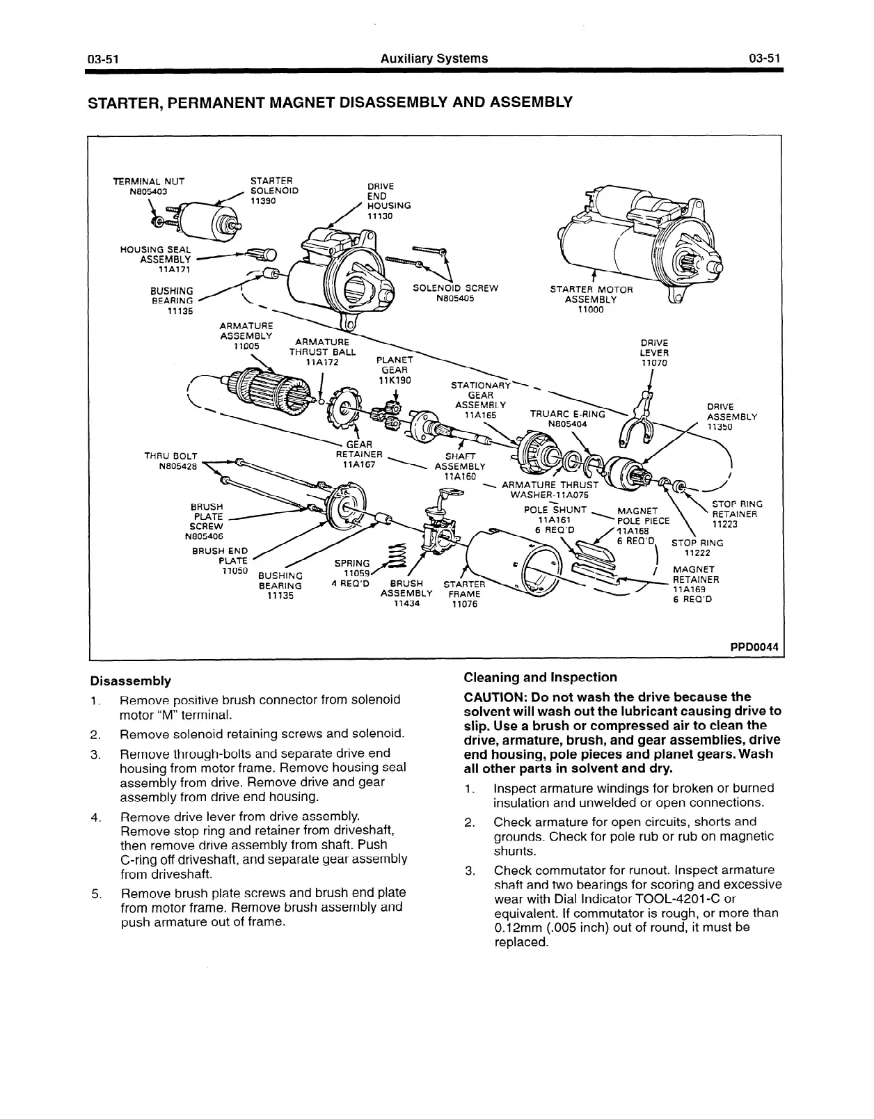
STARTER, PERMANENT MAGNET DISASSEMBLY AND ASSEMBLY
TERMINAL NUT
STARTER
N805403
/ SOLENOID
11390
DRIVE
END
/
HOUSING
11130
HOUSING SEAL
--
WtJcJk
ASSEMBLY -v
llA771
STARTEff’ MOTOR
ASSEMBLY
BUSHING /!
BEARING y \
ARMA-T
ASSEM
77DC
DRIVE
LEVER
GEAR
17K190
STATfONARY. \
GEAR
ASSEMBLY _
DRIVE
ASSEMBLY
TRUARC
RETAINER .
17A767
THRU BOLT
SHAm
\ ASSEMBLY
17A160
N805428 \
STOP
RING
POLE<HUNT -
- - - -----
MAGNET \
b _A. a -.c-c
’ RETAINER
BRUS
PLATE
SCREW
N805406
IwLt rltLt
\
71223
17A168
6 REQ’D
I
STOP RING
11222
BRUSH
END
Pl
ATE
7
7050
i
MAGNET
BUSHING
BEARING
11135
4 REQ’D
BRUSH
STiRTEd
ASSEMBLY
FRAME
71434
11076
PPDOO 44
Disassembly
1.
Remove positive brush connector from solenoid
motor “M” terminal.
2. Remove solenoid retaining screws and solenoid.
3. Remove through-bolts and separate drive end
housing from motor frame. Remove housing seal
assembly from drive. Remove drive and gear
assembly from drive end housing.
4. Remove drive lever from drive assembly.
Remove stop ring and retainer from driveshaft,
then remove drive assembly from shaft. Push
C-ring off driveshaft, and separate gear assembly
from driveshaft.
Cleaning and Inspection
CAUTION: Do not wash the drive because the
solvent will wash out the lubricant causing drive to
slip. Use a brush or compressed air to clean the
drive, armature, brush, and gear assemblies, drive
end housing, pole pieces and planet gears. Wash
all other parts in solvent and dry.
1.
Inspect armature windings for broken or burned
insulation and unwelded or open connections.
2.
Check armature for open circuits, shorts and
grounds. Check for pole rub or rub on magnetic
shunts.
3.
Check commutator for runout. Inspect armature
shaft and two bearings for scoring and excessive
wear with Dial Indicator TOOL-4201-C or
equivalent. If commutator is rough, or more than
0.12mm (.005 inch) out of round, it must be
replaced.
5. Remove brush plate screws and brush end plate
from motor frame. Remove brush assembly and
push armature out of frame.
 Loading...


