03-l 3
Auxiliary Systems
03-I 3
DISTRIBUTORLESS IGNITION SYSTEM REMOVAL AND INSTALLATION (Continued)
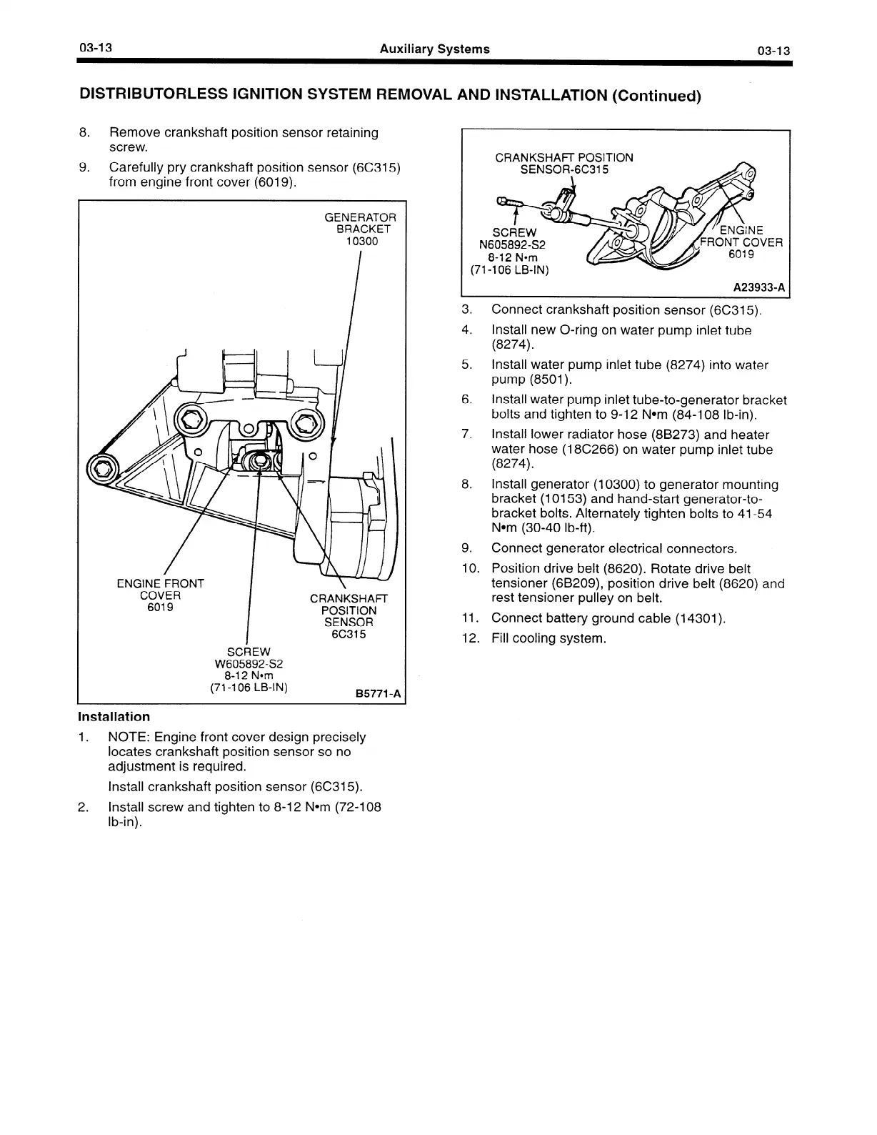
8. Remove crankshaft position sensor retaining
screw.
9. Carefully pry crankshaft position sensor (6C315)
from engine front cover (6019).
GENERATOR
BRACKET
10300
ENGINE FRONT
COVER
6019
CRANKSHAFI-
POSITION
SENSOR
6C315
SCREW
W605892-S2
8-12 Nom
(71-l
06 LB-IN)
95771 -A
Installation
1.
NOTE: Engine front cover design precisely
locates crankshaft position sensor so no
adjustment is required.
Install crankshaft position sensor (6C315).
2. Install screw and tighten to 8-12 Nom (72-l 08
lb-in).
N
(71
CRANKSHAFl- POSITION
-
t
SCREW
SENSOR-6C315
605892-S2
8-12 Narn
-106
LB-IN)
6019
‘ER
A23933-A
3. Connect crankshaft position sensor (6C315).
4. Install new O-ring on water pump inlet tube
(8274).
5. Install water pump inlet tube (8274) into water
pump (8501).
6. Install water pump inlet tube-to-generator bracket
bolts and tighten to 9-12 Nom (84-l 08 lb-in).
7. Install lower radiator hose (88273) and heater
water hose (18C266) on water pump inlet tube
(8274).
8.
Install generator (10300) to generator mounting
bracket (10153) and hand-start generator-to-
bracket bolts. Alternately tighten bolts to 41-54
Nom (30-40 lb-ft).
9. Connect generator electrical connectors.
10. Position drive belt (8620). Rotate drive belt
tensioner (68209), position drive belt (8620) and
rest tensioner pulley on belt.
11.
Connect battery ground cable (14301).
12. Fill cooling system.
 Loading...


