Appendix B: Worksheets
EST iO64 and iO500 Technical Reference Manual 211
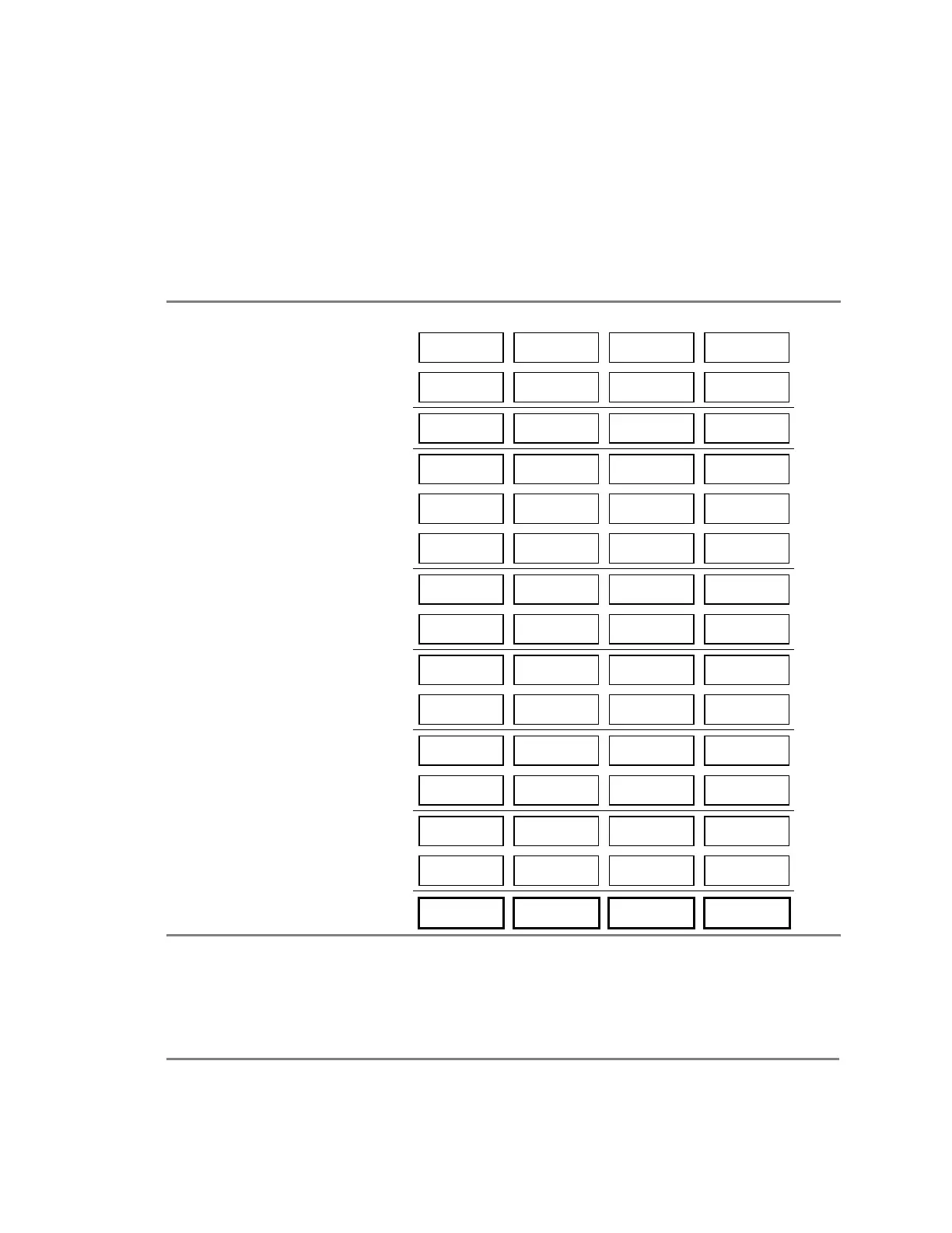
Worksheet method
Use this worksheet to determine the maximum cable length of a
notification appliance circuit for a given number of appliances.
Use this worksheet only if all the appliances are regulated. That is,
they must have a minimum operating voltage of 16 V. For other
appliances, use the “Equation method.”
NAC cable length
NAC1 NAC2 NAC3 NAC4
Total operating current [1]
A
Load factor (64 point panel) ×
0.20
0.20 0.20 0.20
V/A
Load factor (250/500 point panel)
0.24
0.24 0.24 0.24
Load voltage drop =
V
Source voltage
20.4
20.4 20.4 20.4
V
Load voltage drop
V
Minimum voltage =
V
Regulated appliance voltage
16.0
16.0 16.0 16.0
V
Voltage drop [2] =
V
Total operating current ÷
A
Maximum resistance =
Wire resistance (/ft) [3] ÷
Maximum wire length =
ft.
÷
2
2 2 2
Maximum cable length =
ft.
[1] Total of the maximum operating currents for all appliances as specified for FWR power. See the appliance installation
sheets for operating currents.
[2] This voltage drop is valid for regulated notification appliances only. For unregulated appliances, see “Equation method,”
later in this topic.
[3] Use the manufacturer’s published wire resistance expressed in ohms per foot. For typical values, see Table 1, later in this
topic.
 Loading...