Chapter 2: Installation and wiring
66 EST iO64 and iO500 Technical Reference Manual
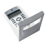
Remote annunciator wiring (TB4)
The control panel provides a connection for up to eight remote
annunciators.
Circuit specifications
• Class B or Class A
• Circuit voltage: 2.55 V peak-to-peak average
• Circuit current: 30 mA max.
• Circuit impedance: Up to 8 annunciators or 4,000 feet
(1,219 m) of 18 AWG wire
• Circuit resistance: 90
• Circuit capacitance: 0.3 µF
• Ground fault impedance: 0 to 5 k
• RS-485 communications speed: 9600 baud
• Wiring: 18 to 14 AWG (1.0 to 2.5 sq. mm) twisted pair
• Max. wire run: 4,000 feet (1,219 m)
Notes
• Refer to the R-Series Remote Annunciators and Expander
Installation and Operation Guide (P/N 3100969) or the R-Series
annunciator installation sheets for detailed wiring information
• Installation limits under jurisdiction of local authority
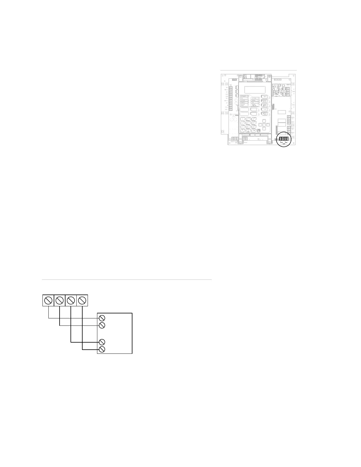
Annunciator channel wiring (Class A)
+
–
TB4
+
–
hannel 1
hannel 2
CH1 (+) IN
CH1 ( ) IN
–
CH2 (+) IN
CH2 ( ) IN
–
Annunciator
Terminal wiring location
 Loading...