Chapter 2: Installation and wiring
78 EST iO64 and iO500 Technical Reference Manual
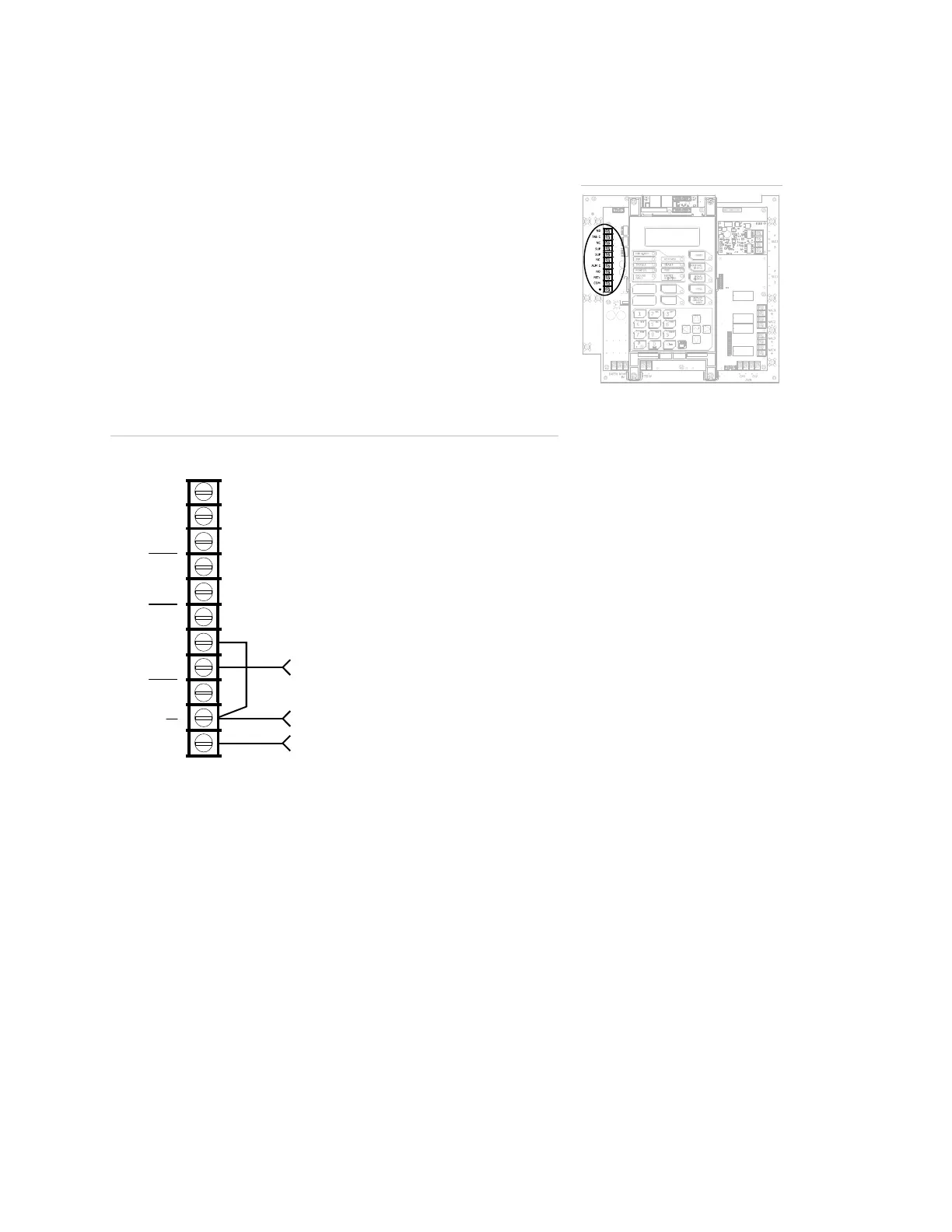
RPM module wiring
The Reverse Polarity Module (RPM) is an interface between the
control panel and a reverse polarity receiver. It provides off-premise
signal transmission for systems that must comply with NFPA
requirements. When used as a reverse polarity remote station
transmitter, it can be connected to either a single circuit (alarm or
alarm and trouble) or up to three circuits (alarm, supervisory, and
trouble). Below are application diagrams for using the RPM module.
For detailed information and wiring, refer to the RPM Installation
Sheet (P/N 3100430).
Note: The RPM must be mounted in an MFC-A enclosure
immediately adjacent to the panel and in conduit.
Alarm transmitted only
TRBL
C
NC
SUP
NC
ALM
24VOUT
ontrol panel
TB3
+
NO
From COM on RPM (black wire)
From +24 on RPM (red wire)
C
NO
+
From ALRM on RPM (brown wire
Terminal wiring location
 Loading...