Chapter 2: Installation and wiring
54 EST iO64 and iO500 Technical Reference Manual
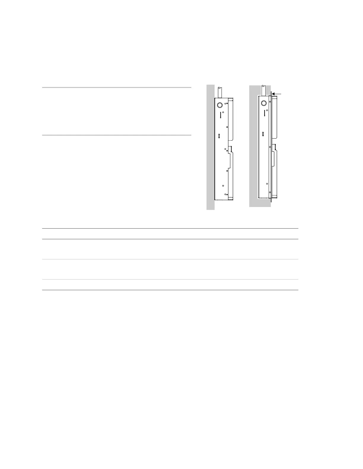
Cabinet box installation
The cabinet box can be surfaced mounted or semiflush mounted.
To surface mount the cabinet box:
1. Position the cabinet box on the finished wall surface.
2. Fasten the cabinet box to the wall surface where
indicated.
To semiflush mount the cabinet box:
1. Frame the interior wall as required to support the full
weight of the cabinet and standby batteries.
2. Install a semiflush trim ring (optional) to the cabinet.
3. Fasten the cabinet box to the framing studs where
indicated.
Surface mount Semiflush mount
Trim rin
Backbox and backbox with door dimensions
Model D1 [1] D2 D3 D4 D5 [1] D6 D7 D8 D9
64 pt. 21.50 in.
(54.6 cm)
3.85 in.
(9.8 cm)
7.5 in.
(19 cm)
15.50 in.
(39.4 cm)
14.25 in.
(36.2 cm)
10.25 in.
(26 cm)
4.5 in.
(11.4 cm)
21.7 in.
(55.1 cm)
2.7 in.
(6.8 cm)
250/500
pt.
28.0 in.
(71.1 cm)
3.85 in.
(9.8 cm)
9.0 in.
(22.8 cm)
22.0 in.
(55.8 cm)
15.75 in.
(40.0 cm)
10.25 in.
(26.0 cm)
4.4 in.
(11.1 cm)
28.2 in.
(71.6 cm)
2.7 in.
(6.8 cm)
[1] Add 1-1/2 in. (3.81 cm) to D1 and D5 dimensions for trim kit.
 Loading...