Chapter 2: Installation and wiring
74 EST iO64 and iO500 Technical Reference Manual
SA-CLA wiring
The wiring connections on the optional Class A card are only used
when wiring NACs Class A on a 64 point control panel.
Circuit specifications
• Operating current
Standby: 3 mA
Alarm/Max.: 60 mA
• Max. resistance: 26
• Max. capacitance: 0.35 µF
• Max. current: 2.5 A per circuit
• Ground fault impedance: 0 to 5 k
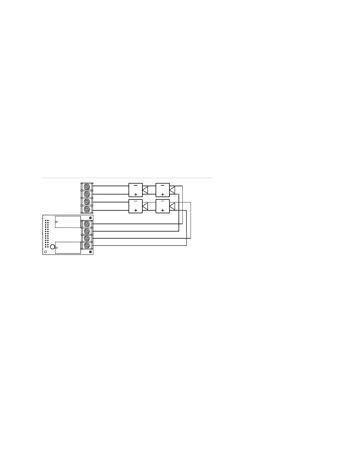
SA-CLA wiring
Class A card installed
on main circuit board
NA
1–
NAC2+
NAC2–
NAC1+
+
+
TB2 on main
circuit board
 Loading...