Chapter 2: Installation and wiring
EST iO64 and iO500 Technical Reference Manual 63
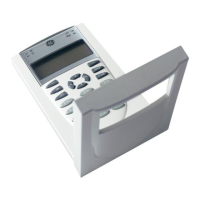
Device loop wiring
The control panel provides one device loop circuit that can be used
with detectors and modules. Refer to the "Control panel
specifications" for the number of devices (device addresses) that
can be wired on a loop. The loop circuit is supervised for opens,
shorts, and grounds.
Note: For a complete list of devices that can be connected to this
circuit, refer to the iO64 and iO500 Series Compatibility List (P/N
3101064).
Circuit specifications
• Class B or Class A
• Communication line voltage: Maximum 20.6 V peak-to-peak
• Circuit current: 0.5 A max.
• Max. total resistance: 66
• Max. total capacitance: 0.5 µF
• Max. resistance between isolators: Limited only by overall wire
run lengths
• 64 isolators maximum (total both isolator bases and modules)
• Ground fault impedance: 0 to 5 k
• Signal synchronization is supported on a system-wide basis (all
device loops) when using SIGA-CC1S or SIGA-MCC1S
addressable NAC modules and Genesis or Enhanced Integrity
notification appliances.
Note: Installation limits under jurisdiction of local authority.
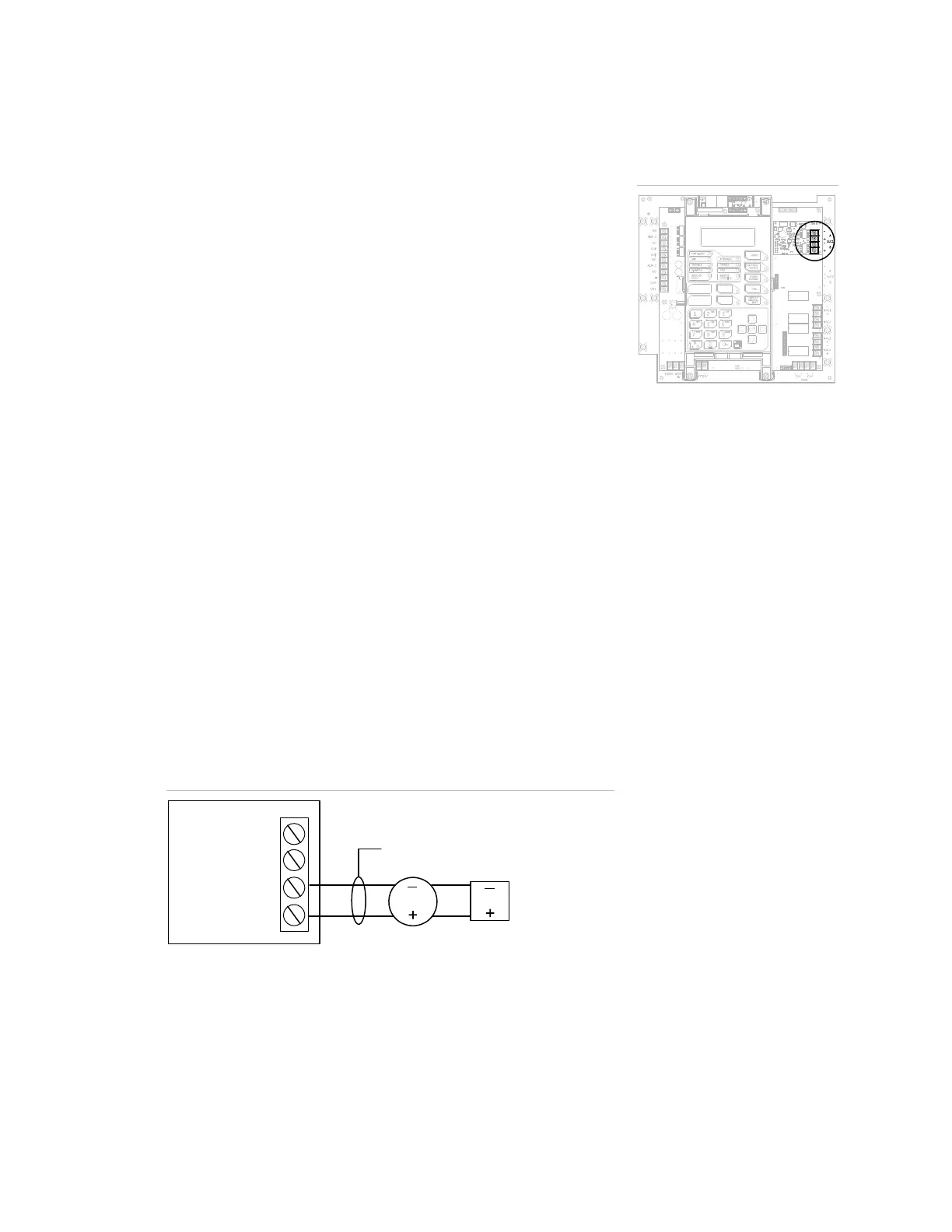
Class B wiring (Style 4)
Loop SEC
Loop card
+
–
Loop PRI
+
–
Loop
device
Loop
devic
Data line
Terminal wiring location
 Loading...