Chapter 2: Installation and wiring
60 EST iO64 and iO500 Technical Reference Manual
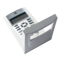
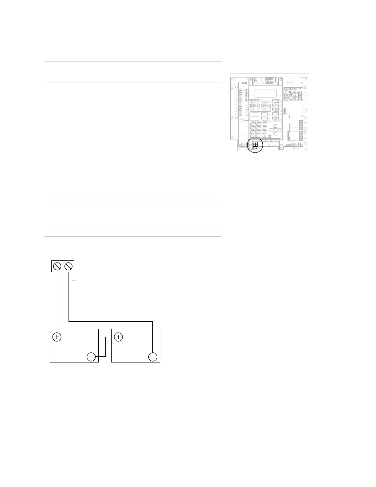
Battery wiring (TB8)
Caution: Connect and disconnect standby batteries only with the AC
power applied.
The control panel has a 24 VDC rechargeable battery circuit that is
capable of charging up to two 26 Ah sealed lead acid batteries.
The table below lists the batteries that can be installed in the control
panel cabinets. Up to two 10 Ah batteries will fit in the 64 point
control panel cabinet and two 18 Ah batteries will fit in the 250/500
point control panel cabinet. If larger batteries are required, you must
use a GE Security battery cabinet. To determine which battery your
system requires, use the "Battery calculation worksheet" in the
worksheets appendix.
Model Manufacturer Rating
12V4A GS Battery, Inc. 12 volts, 4.5 ampere-hours
12V6A5 GS Battery, Inc. 12 volts, 7.2 ampere-hours
12V10A GS Battery, Inc. 12 volts, 11 ampere-hours
12V17A GS Battery, Inc. 12 volts, 18 ampere-hours
12V24A GS Battery, Inc. 12 volts, 26 ampere-hours
Battery wiring
TB8
Red
Black
12 VDC
Battery
12 VDC
Battery
+
Terminal wiring location
 Loading...