Chapter 1: System operation
EST iO64 and iO500 Technical Reference Manual 13
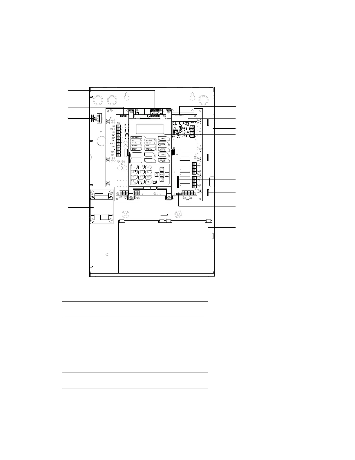
Component descriptions
The control panel contains the following components.
Component layout
1
2
3
4
5
8
7
9
10
6
11
12
1
00:00:00 01/01/07
,
Item Description
1 Transformer: Changes 120 or 230 volt AC supply voltage to 24
volt AC
2 Main AC wiring block and fuse holder: Provides connections
for 120 or 230 volt AC (primary power) from dedicated service.
Includes a primary power fuse (5 A).
3 RS-232 card connector (J3): Provides a connection for the
optional RS-232 card for connecting a printer or downloading
from the configuration utility
4 Dialer card connection (J8)
5 Ethernet card connector (J1): Provides a connection for the
optional ethernet card
6 Main circuit board: Provides connections for all circuits. Also
includes the operator interface.
 Loading...