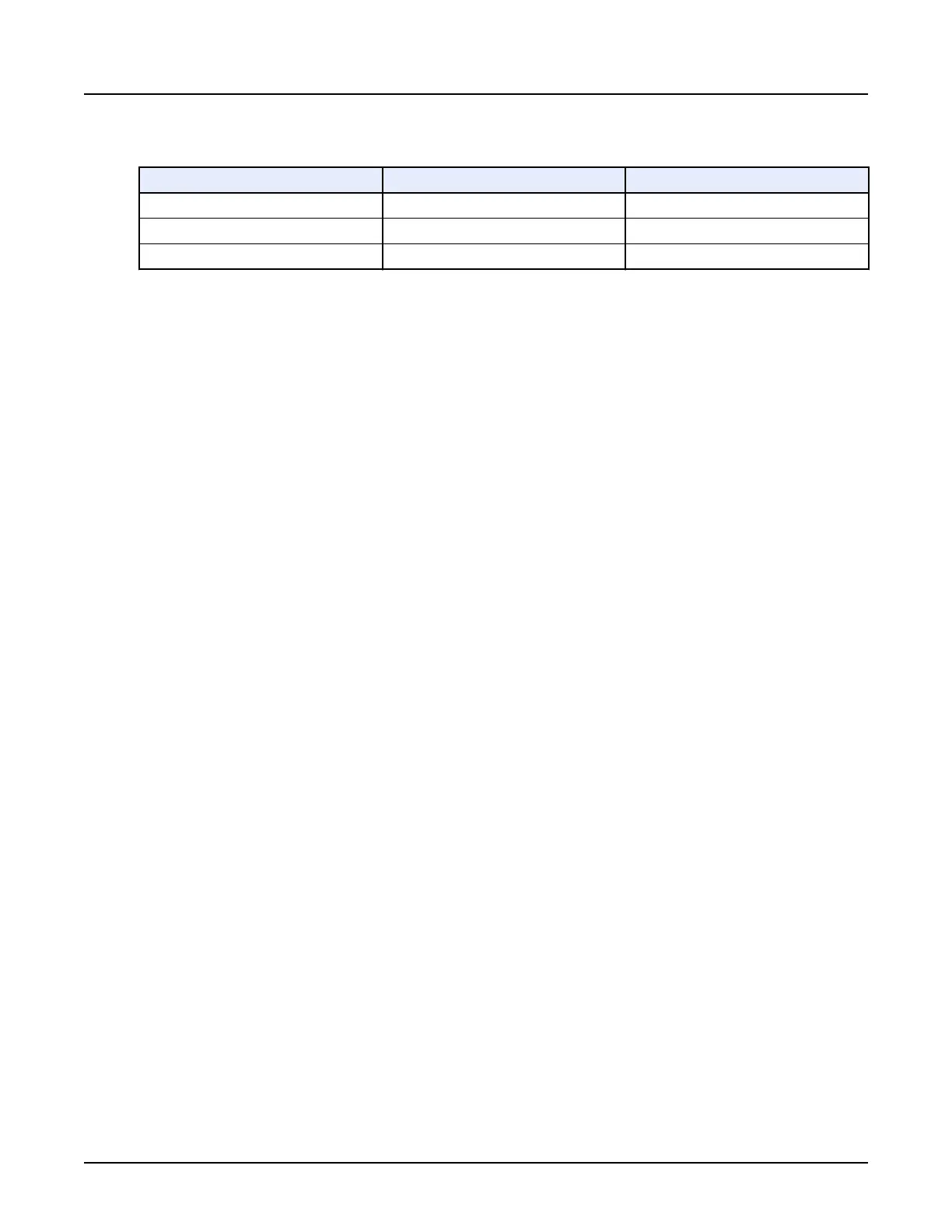
Table 13: Beam Collimation
Detector Configuration Beam Collimation Pitch
64 × 0.625 40.0 mm 0.5:1, 0.9:1 interleaved helices
64 × 0.625 40.0 mm 1.375:1 interspaced helices
128 × 0.625 80.0 mm 0.9:1 interleaved helices
Interleaved helices minimize helical artifact and give the best detail. Interspaced helices have
more interpolated data and increased helical artifact when compared to interleaved mode. Using
interspaced helices compared to interleaved helices will provide lower dose.
5.5 Detector configuration
Parameter selections in the Coverage Collection determine the detector configuration.
5.5.1 Axial
The parameters selected to set the detector coverage (detector configuration) determine the
slice thickness and speed.
•
Beam Collimation or detector coverage allows selection of 5, 40, 80, 120, 140, and 160 mm.
•
Axial slice thickness choices range from 0.625 to 5.0 mm thick.
•
Number of images per rotation is equal to the detector coverage divided by the slice
thickness.
•
Rotation Speed can be adjusted to optimize acquisition time. Rotation Speeds are 0.28,
0.35, 0.5, and 1.0 seconds.
5.5.2 Helical
There are five main parameter selections for helical.
•
Detector Coverage determines the beam collimation, 40.0 mm or 80 mm, in the Z direction.
•
Helical Thickness determines the primary and secondary reconned image slice thickness.
•
Slice thickness choices range from 0.625 mm to 5.0 mm.
•
Pitch, detector coverage and rotation time used determines the speed of the table per gantry
rotation. There are two pitch selections with associated table speed.
•
Rotation Time determines the speed the gantry rotates in 360°.
Revolution CT User Manual
Direction 5480385-1EN, Revision 1
184 5 Hardware Components

 Loading...