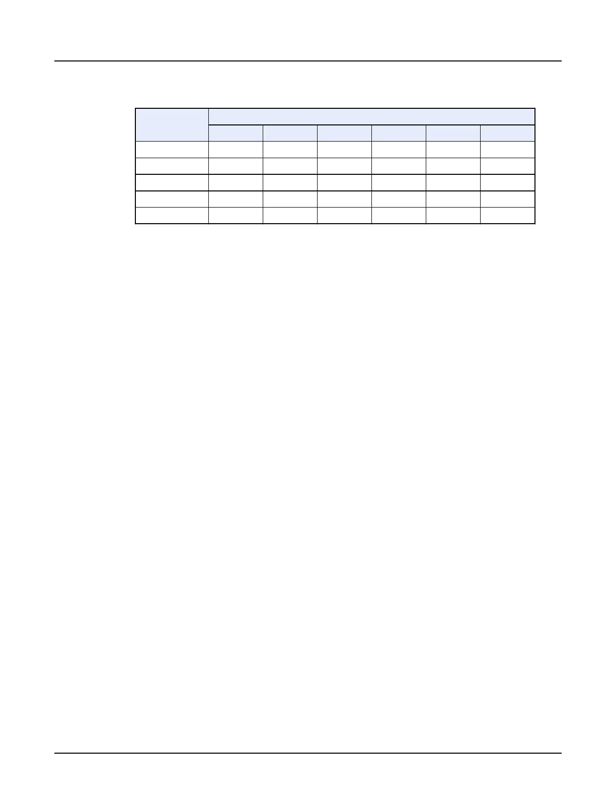
Table 20: Images per Rotation
Slice Thickness
(mm)
Detector Coverage (mm)
5 40 80 120 140 160
5 1i 8i 16i 24i 28i 32i
2.5 2i 16i 32i 48i 56i 64i
1.25 4i 32i 64i 96i 112i 128i
0.625 NA 64i 128i 192i 224i 256i
0.625z NA 128i 256i 384i 448i 512i
○
The choice for one determines the choices for the other. Some combinations are not
allowed.
○
The choice of detector coverage and slice thickness determines the images per rotation.
Some combinations are not allowed.
5. For an Axial or Cine scan type, the interval is set equal to the detector coverage. The
interval value can be increased or decreased. If the interval is greater than the detector
coverage, the gap is between each rotation of data, not between the slices.
For an Axial scan type, the interval or spacing defaults to the equal number of images per
rotations multiplied by the slice thickness.
○
The interval for Axial scanning can be zero, equal to, or greater than the width of the
detector configuration.
○
Axial interval with skip refers to a gap between scan groups. This can be useful, for
example, when performing a survey exam, such as a high resolution chest exam.
6. Note the Total Exposure Time.
7. Click [Apply].
NOTE: The Total Exposure Time shown in the
Coverage Speed
collection does not account
for the interscan delay prescribed in the protocol.
4.5.3 Set the kV and mA Control
Use one of the following procedures to set the kV for the imaging study.
4.5.3.1 Set the mA
Use this procedure to set the mA for the scan prescription.
1.
From the
Scan Settings
window, click
kV and mA Control
.
2. Choose an
mA Mode
.
○
Set to
Manual mA
and enter an mA value.
○
Set to
SmartmA
or
SmartmA and ODM
to enable mA modulation in the x-y and z-
directions.
■
Select a Noise Index value that provides acceptable diagnostic quality. As the Noise
Index increases the required mA decreases and image noise increases. The
Revolution CT User Manual
Direction 5480385-1EN, Revision 1
Chapter 11 Scan 281