HEIDENHAIN MANUALplus 4110 Graphic Simulation 10.1
Types of simulation
The graphic simulation feature enables you to check the machining sequence, the proportioning
of cuts and the finished contour before actual machining. In the “Teach-in” mode, this function
simulates the execution of a single cycle—in “Program run” mode it simulates a complete cycle
or DIN program.
The simulation supports the following views:
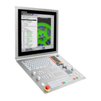
Wire frame graphics
The MANUALplus 4110 draws the traverse paths as lines. The theoretical tool tip is the
reference point. This view is well suited for showing machining passes.
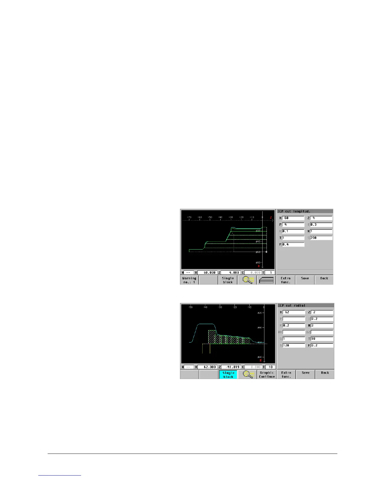
Cutting path graphics
In this view the cutter geometry of the tool is taken into consideration. Here you can check if
material remains, or if the contour is damaged.
Machining simulation
The blank is displayed as a white surface which is machined during the simulation (“erasing
graphics”).
Tool tip: For the wire frame and cutting path graphics you specify whether the tool tip is to be
shown, or whether the theoretical tip should be represent by a dot of light.
Wire frame graphics: Without display of
the tool tip. The dot of light (small
rectangle) represents the theoretical tool
point.
Cutting path graphics: With display of
the tool tip.

 Loading...