Home
HEIDENHAIN
Control Panel
MANUALPLUS 4110
HEIDENHAIN MANUALPLUS 4110 User Manual
5
of 1
of 1 rating
156 pages
Give review
Manual
Specs
To Next Page
To Next Page
To Previous Page
To Previous Page
Loading...
HEIDENHAIN MANUALplus 4110 Linear
Machining Example
7.2
Cr
eat
e the “Threaded st
ud” c
ycle pr
ogram
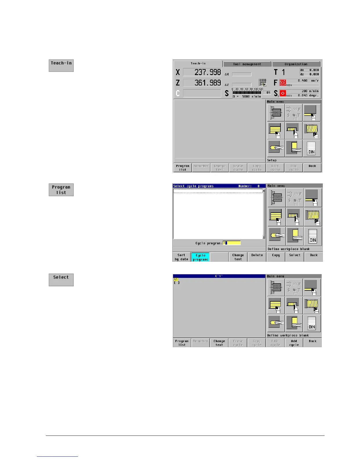
Creating a cycle program
Activate the teach-in mode:
Press the
Teach-in
soft key
Call the program list:
Press the
Program list
soft
key
Enter program number “1”
for
Cycle program
Call cycle program “1”
Press the
Select
soft key
67
69
Table of Contents
Contents
3
Axis Directions
5
Reference Points
5
Traverse Motions
5
Tool in Front of or Behind the Workpiece
6
The Coordinate System
7
Two-Dimensional Coordinate System
7
C Axis
7
Accuracy
7
Tool-Tip Radius Compensation (TRC)
8
Feed Rate
9
Spindle Speed
9
Constant Spindle Speed
9
Constant Cutting Speed
9
Data Input Keypad
11
Soft Keys as Toggle Switches
13
Menu Selection (9-Field Box)
13
Soft Keys
13
Machine Data Display
14
Position Display
14
Display of X and Z Position
14
Distance-To-Go Display
14
Feed Rate Display Element
15
Set the Feed Rate
15
Feed Rate Display
15
Protection Zone Status
15
Spindle Display Element
16
Display for Positioning of Spindle
16
Driven Tool
16
Setting the Cutting Speed or Spindle Speed
16
Tool Display Element
17
One Tool Holder (Two-Digit T Display)
17
Turret or Automatic Tool Changer (Four-Digit T Display)
17
Switching on the Machine
18
Axis and Spindle Enabling
18
Sequence for Reference Run
19
Traversing the Reference Marks
19
Confirm Tool
20
Switching the Operating Mode
21
Error Messages and PLC Status Information
22
Processing Error Messages
22
Processing PLC Status Displays
22
Switching between the Error Window and the PLC Status Display
22
Switching the Manualplus 4110 off
23
Tool Measurement
25
Creating Tool T1
25
Tool Data
25
Specify the Position in the Tool Manager
26
Enter the Tool Data
26
Enter the Tool Description
27
Overview of Tool Data T1
28
Create Tool T2 by Copying
29
Copying
29
Assume Tool Data and Specify the Position in the Tool Manager
29
Tool Orientation WO: 1
30
Adapt Tool Data
30
Overview of Tool Data T2
30
Tool Angle A: 93
30
Tip Angle B
30
Wear Compensation DX in X: 0 MM Wear Compensation DZ in Z: 0 MM
30
Adapt the Tool Data
32
Setup Dimension Z in Z: 0 MM
37
Tool Orientation wo
37
Wear Compensation DX in X: 0 MM Wear Compensation DZ in Z: 0 MM
37
Machining Direction MD M3=3, M4=4
38
Prepare the Machine
41
Entering the Machine Data
41
Specify the Workpiece Datum
43
Facing a Surface
44
Setting Dimensions for T1
45
Call the “Measure Tool” Function
45
Producing the Measuring Diameter
46
Enter the Setting Dimensions
46
Determine Setting Dimensions for T2
47
Activate Tool T2
47
Touch the Measuring Diameter with the Tool
49
Touch the End Face with the Tool
49
Activate Tool T6
50
Setting Dimensions for T6
50
Entries and Assumed Machine Data
51
Setting Dimensions for T8
53
Activate Tool T8
53
Setting Dimensions for T10
56
Activate Tool T10
56
Machine Setup
59
Set the Workpiece Datum
61
Setting the Protection Zone
63
Approach the Protection Zone
64
Defining the Tool Change Position
65
Approach the Tool Change Position
66
“Threaded Stud” Example Program
67
Creating a Cycle Program
68
Program the “Icp–Longitudinal Cutting” Cycle
71
Assume the Tool and Technology Data from the Tool File
72
Contour Element 1 (Chamfer)
73
Call the ICP Editor
73
ICP Contour “Threaded Stud”
73
Describe the Contour Element
74
Contour Element 2 (Thread Undercut)
74
Contour Element 3 (Oblique Cut)
75
Contour Element 4 (Horizontal Line)
76
Contour Element 5 (Rounding)
77
Contour Element 6 (Vertical Line)
77
Contour Element 7 (Chamfer)
78
Contour Element 8 (Horizontal Line):
79
Contour Element 9 (Vertical Line)
79
Enter the Contour Name
80
Conclude and Test the “ICP Cutting Longitudinal” Cycle
82
Warnings
82
Run the Cycle
83
Program the “Approach Tool Change Position” Cycle
84
Create the “ICP Finishing Longitudinal” Cycle by Copying
86
Adapt the Cycle
87
Cycle Parameters
87
Run a Graphic Simulation of the Cycle
88
Create the “Threaded Stud” Cycle Program
88
Select Tool Compensation
90
Perform the Tool Compensation
90
Repeat the “ICP Finishing Longitudinal” Cycle
91
Program the “Threading Cycle”
93
Repeat the Last Thread Cut with the Corrected Tool
98
Create the “Matrix” Cycle Program
103
“Matrix” Example Program
103
Program the Cycle “ICP Cutting Transverse”
105
Program the Cycle “ICP Finishing Longitudinal”
108
Create the Matrix ICP Contour
113
Create the “Matrix” ICP Contour
114
Create the “Form Roll” Cycle Program
125
“Form Roll” Example Program
125
Program Cycle Blank—Bar/Tube
126
Run Graphic Simulation of Cycle
128
Create the ICP Contour “Form Roll”
141
Cutting Path Graphics
145
Wire Frame Graphics
145
Types of Simulation
145
Setting the Type of Simulation
146
Zoom Functions
147
Change the Image Section
147
Extend the View
148
Actions before Executing a Program
149
Activate Program Run
149
Select the New Program
150
Run a Graphic Simulation of the Program
151
Checking the Cycle
151
Run Cycles Individually
152
Run the Cycle Program (for each Cycle)
152
Interrupt the Program Run
153
Initial Situation
153
Tool Compensation
153
Measure the Workpiece
154
Entering Tool Compensation Values
154
Repeat the Finishing Cycle with the Corrected Tool
155
5
Based on 1 rating
Ask a question
Give review
Questions and Answers:
Need help?
Do you have a question about the HEIDENHAIN MANUALPLUS 4110 and is the answer not in the manual?
Ask a question
HEIDENHAIN MANUALPLUS 4110 Specifications
General
Brand
HEIDENHAIN
Model
MANUALPLUS 4110
Category
Control Panel
Language
English
Related product manuals
HEIDENHAIN TNC 640
948 pages
ITNC 530 - 6-2010 DIN-ISO PROGRAMMING
618 pages
ITNC 530 - CYCLE PROGRAMMING
513 pages
HEIDENHAIN 548431-05
722 pages

 Loading...