Step 8 Install the cover. For details, see Installing the Cover of a G530 V2.
Step 9 Install the G530 V2. For details, see 4.4.4 Installing a G530 V2.
Step 10 Power on the G530 V2. For details, see 3.2 Powering On the Compute Node.
----End
6.5 GP316 Optional Part Installation
6.5.1 Riser Card Tray
Installing a Riser Card Tray
Step 1 Power off the GP316. For details, see 3.1 Powering Off the Compute Node.
Step 2 Remove the GP316. For details, see 3.6 Removing a GP316.
Step 3 Place the GP316 on the ESD floor.
Step 4 Remove the cover. For details, see Removing the Cover of a GP316.
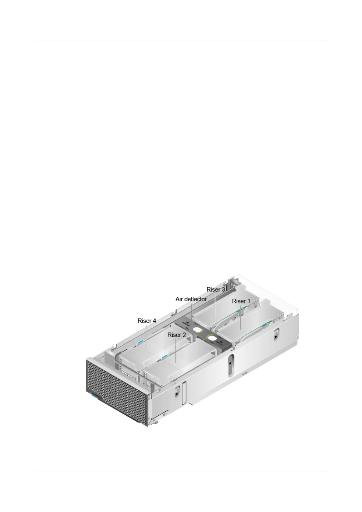
Step 5 Determine the location for installing the riser card tray.
Figure 6-43 shows the numbering and locations of the riser card trays.
Figure 6-43 Numbering and locations of the riser card trays
Step 6 Take a spare riser card tray out of its ESD bag.
Step 7 Vertically insert the riser card tray downwards into the slot. See (1) in Figure 6-44.
FusionServer G5500 Server
User Guide
6 Optional Part Installation
Issue 02 (2017-12-15) Huawei Proprietary and Confidential
Copyright © Huawei Technologies Co., Ltd.
161
 Loading...