4. Close the ejector lever on the GP316. See (4) in Figure 4-17.
----End
4.4.4 Installing a G530 V2
Context
To make full use of the space and prevent the GP316 from being removed forcibly, the upper
layer GP316 and the lower layer G530 V2 adopt dislocation design. Therefore, you must
install the GP316 at the upper layer and then install the G530 V2 at the lower layer.
Procedure
Step 1 Install a GP316 before installing a G530 V2. For details, see 4.4.3 Installing a GP316.
Step 2 Unpack the packing case.
1. Check whether the packing case and seals are in good conditions.
NOTE
If there is any damage (for example, the package is soaked or deformed, or the seals or pressure-
sensitive adhesive tapes are not intact), submit a Cargo Problem Feedback Form.
2. Use a box cutter to cut the pressure-sensitive adhesive tape on the packing case.
CAUTION
Be careful with the box cutter to avoid personal injury or equipment damage.
3. Unpack the G530 V2.
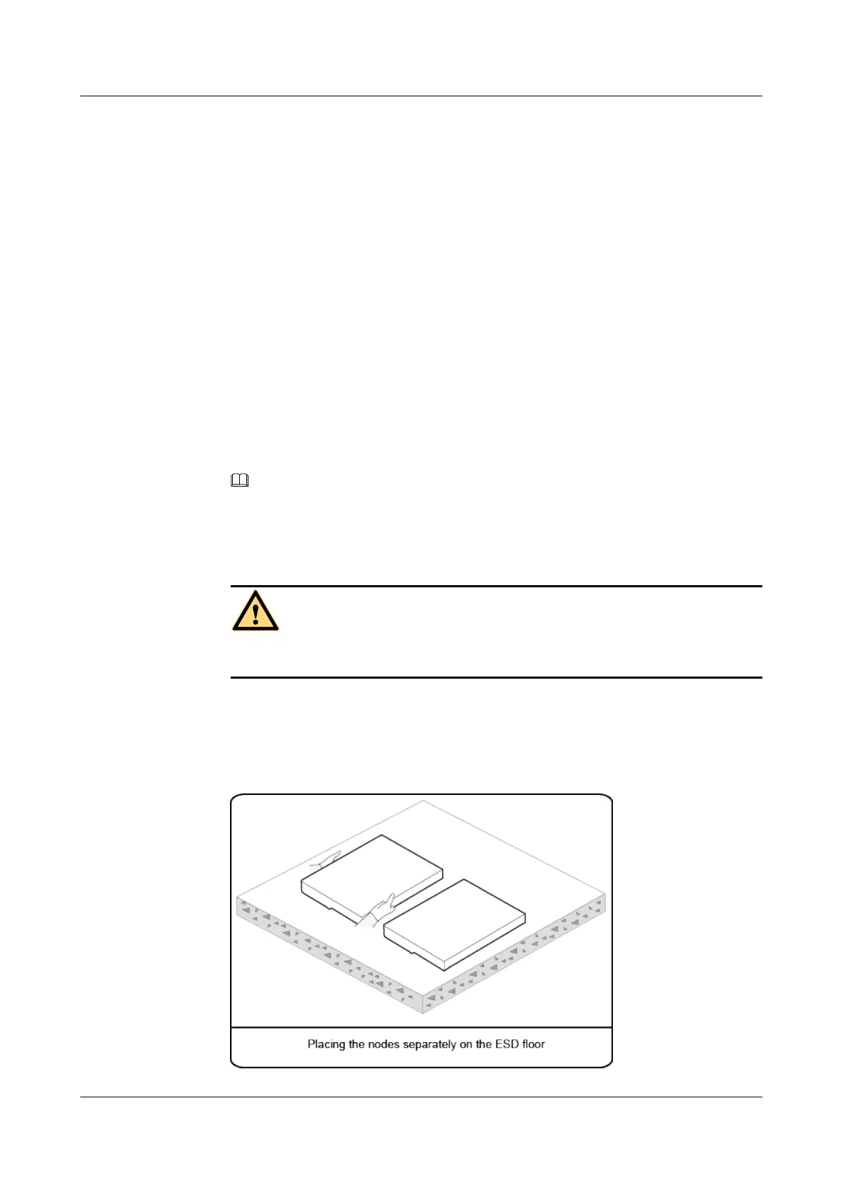
4. If there are multiple G530 V2 nodes, take them out from ESD bags and place them
separately on the ESD floor, as shown in Figure 4-18.
Figure 4-18 Correct operation
FusionServer G5500 Server
User Guide
4 Setup
Issue 02 (2017-12-15) Huawei Proprietary and Confidential
Copyright © Huawei Technologies Co., Ltd.
63
 Loading...