PCIe
Device
CPU PCIe
Standard
Connecto
r
Bandwid
th
Bus
Width
Port
Number
Slot Size
I/O slot
2/4
CPU 2 PCIe 3.0 x16 x16 Port 2A Half-
height
half-
length
single-
width card
NOTE
The expansion slot and riser 3 slot 1 cannot be enabled at the same time. One of the two slots can be
enabled by software programming. By default, the expansion slot is disabled.
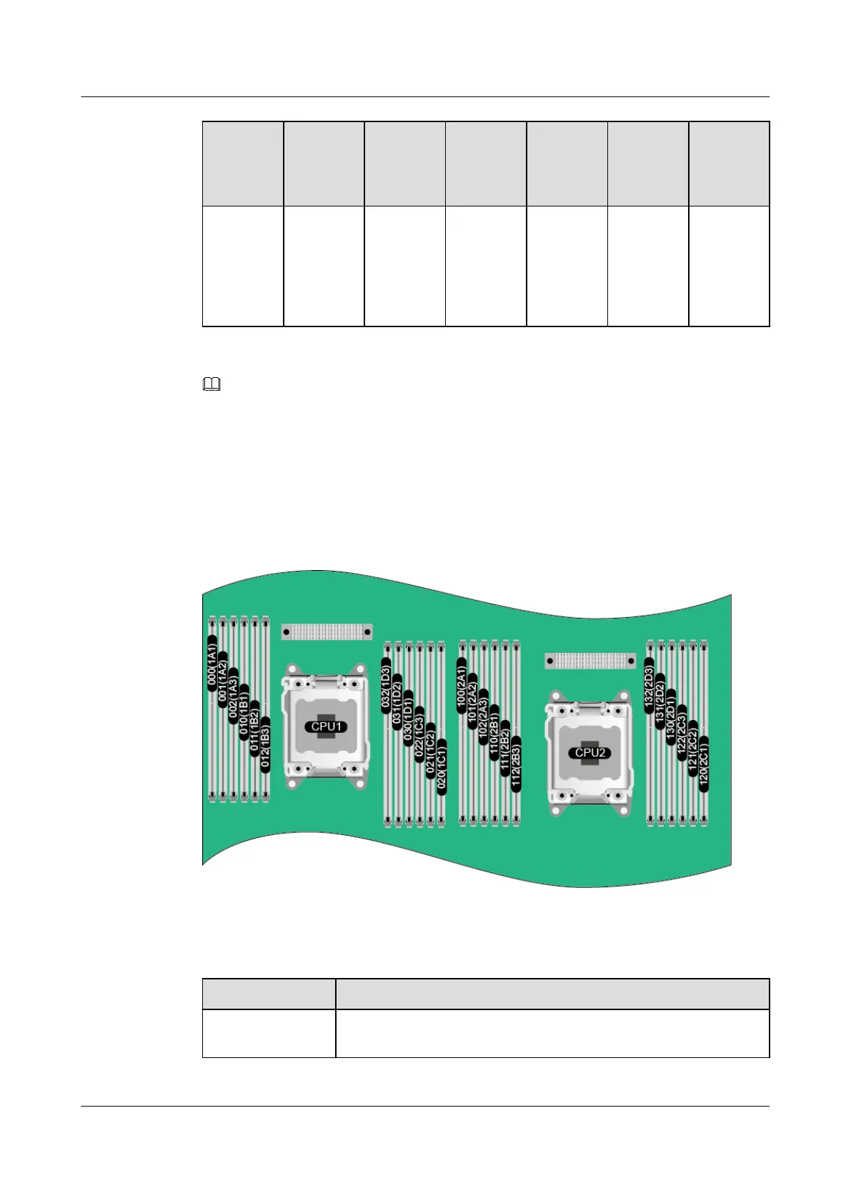
2.7.2 DIMM Slots
The G560 of the G5500 supports a maximum of 24 DIMMs. Figure 2-20 shows the DIMM
slot locations and Table 2-7 lists the DIMM installation sequence.
Figure 2-20 DIMM slot locations
Table 2-7 DIMM installation sequence
CPU
DIMM Installation Sequence
CPU 1 and CPU 2 1A1, 2A1, 1B1, 2B1, 1C1, 2C1, 1D1, 2D1, 1A2, 2A2, 1B2, 2B2,
1C2, 2C2, 1D2, 2D2, 1A3, 2A3, 1B3, 2B3, 1C3, 2C3, 1D3, 2D3
FusionServer G5500 Server
User Guide
2 Components
Issue 02 (2017-12-15) Huawei Proprietary and Confidential
Copyright © Huawei Technologies Co., Ltd.
29
 Loading...