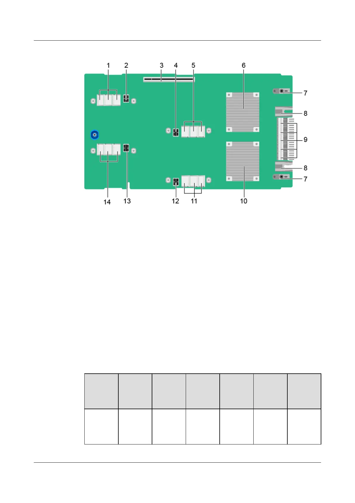
Figure 2-19 GP316 PCIe board components
1 Signal connector of riser 4 2 Power connector of riser 4
3 Expansion slot 4 Power connector of riser 3
5 Signal connector of riser 3 6 PCIe switch 2
7 Backplane guide sleeve 8 Backplane power connector
9 Backplane signal connector 10 PCIe switch 1
11 Signal connector of riser 1 12 Power connector of riser 1
13 Power connector of riser 2 14 Signal connector of riser 2
2.7.1 PCIe Slots
The following tables describe the mapping between the PCIe slots and the CPUs and
mezzanine cards, and list the PCIe standards.
Table 2-3 G560 PCIe slot description
PCIe
Device
CPU PCIe
Standard
Connecto
r
Bandwid
th
Bus
Width
Port
Number
Slot Size
Mezzanin
e card 1
CPU 1 PCIe 3.0 Two x16 Two x16 Port 3A
(through
PCIe
switch)
Non-
standard
device
FusionServer G5500 Server
User Guide
2 Components
Issue 02 (2017-12-15) Huawei Proprietary and Confidential
Copyright © Huawei Technologies Co., Ltd.
22
 Loading...