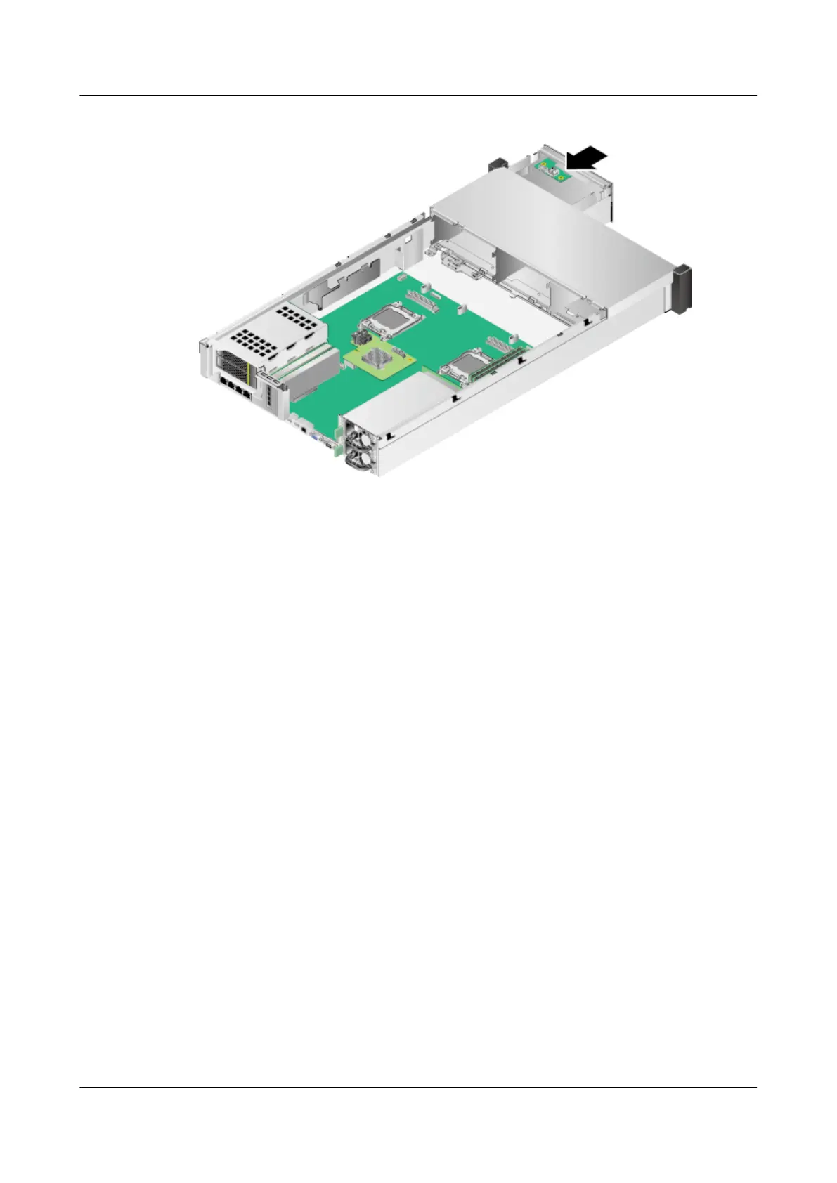
Figure 7-121 Installing an LCD support
Step 11 Connect the cable between the LCD and the VGA port. See step (3) in Figure
7-116.
Step 12 Install the fan support.
Step 13 Install the fan modules. For details, see 7.16 Installing a Fan Module.
Step 14 Install the air duct. For details, see 7.14 Installing the Air Duct.
Step 15 Install full-height full-length riser cards if they are required. For details, see 7.20
Installing a Riser Card.
Step 16 Install the chassis cover. For details, see 7.12 Installing the Chassis Cover.
Step 17 Install the RH2288H V3. For details, see 3.4 Installing the Server.
Step 18 Connect all external cables such as power and network cables. For details, see 3.5
Connecting External Cables.
Step 19 Power on the RH2288H V3. For details, see 4.1 Powering On the Server.
----End
7.49 Removing a SATADOM
Remove a SATADOM if it has failed.
Procedure
Step 1 Wear an ESD wrist strap. For details, see 1 Safety Instructions.
Step 2 Determine the cabinet number and chassis number of the server, and label its
panel to prevent misoperations.
RH2288H V3 Server
User Guide 7 Replacing Parts
Issue 46 (2022-12-28) Copyright © Huawei Technologies Co., Ltd. 256
 Loading...