QVM6800+ Installation and Operation Manual 3
Chapter 1: Introduction
Module Description
Front Module
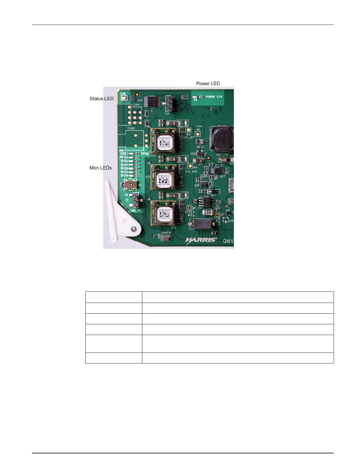
Figure 1-1 shows the position of the LEDs on the card edge of the QVM6800+ front module.
Figure 1-1. QVM6800+ Front Module
Table 1-1 on page 3 briefly describes the QVM6800+ LEDs and switches.
Table 1-1. QVM6800+
Module Features
Feature Description
Status LED Colors indicate module state. See “Card Edge Controls and LEDs” on page 47.
Power LED 3.3V regulator LED. See “Card Edge Controls and LEDs” on page 47
Monitoring LEDs Function and I/P status. See “Monitoring LEDs” on page 48.
J11 Serial port for firmware update. See Appendix 7: “Connectors and Cables” on
page 57
SW 3 Not used.
 Loading...