QVM6800+ Installation and Operation Manual 4
Chapter 1: Introduction
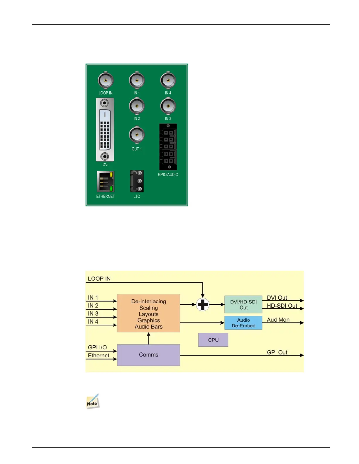
Back Modules
Figure 1-2 shows the triple-slot back module used by the QVM6800+ C modules. Modules
cannot be installed in frames without fans, or in FR6802+DM and 6800/7000 series frames.
Figure 1-2. QVM6800+ C Back Connector
For connector pinout and cable wiring instructions refer to Appendix 7: “Connectors and
Cables” on page 57.
Signal Flow Diagram
The functional block diagram for the cascade QVM6800+.
Figure 1-3. Signal Flow for QVM6800+ cascade version
The the basic QVM6800+ lacks the LOOP IN connector.
 Loading...