QVM6800+ Installation and Operation Manual 9
Chapter 2: Installation
Installing QVM6800+ Series Modules
QVM6800+ series modules have triple-width back connectors. Due to high levels of heat
dissipation, QVM6800+ series modules must not be installed in frames without fans. The
modules cannot be installed in FR6802+DM and 6800/7000 series frames.
Do not install QVM6800+ series modules in slots 6 or 14 because the heat sink and or
audio option board will interfere with the frame.
These modules require no specialized installation or removal procedures.
Ensure that the back connector is installed before inserting the front module. Likewise,
ensure that the front module is unplugged from the frame before removing the back
connector.
See the FR6802
+
Frames Installation and Operation Manual for information about installing
and operating an FR6802+ frame and its components.
A FR6802+RM (Rear Support Extension Rails for 6800+ series frames) option is
recommended for the QVM6800+ series modules. See your FR6802+ Frame Installation and
Operation Manual for installation instructions.
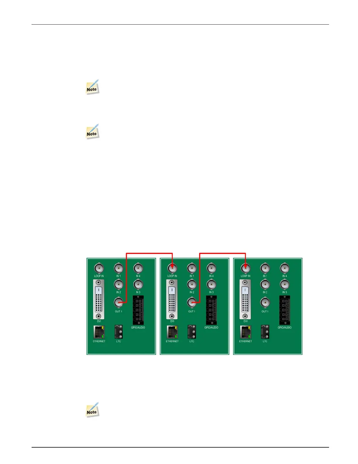
Building a Cascade System
A cascade system is built by connecting the HD-SDI output of one QVM6800+ C module to
the LOOP IN connector of another QVM6800+ C module until all modules in the system are
connected.
Figure 2-1. Cabling a Cascade System (3 x QVM6800+ C back I/O view)
In the example above, the HD-SDI output is always connected to the adjacent QVM6800+ C
module working from left to right, as it results in minimum cable lengths and neat wiring. In
practice cascade systems may be built with any equivalent cabling scheme.
The mapping of inputs to a single virtual layout is accomplished using ZConfigurator; see
“Working with Cascade Systems” on page 14.
 Loading...