QVM6800+ Installation and Operation Manual 59
Chapter 7: Connectors and Cables
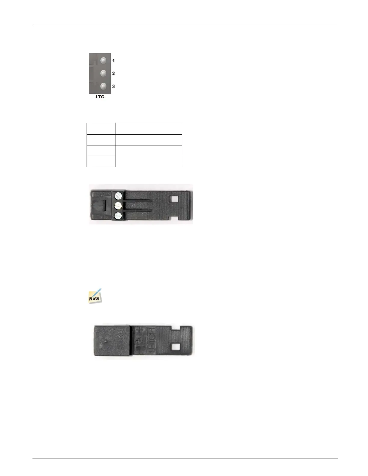
LTC Connector
Figure 7-3. LTC Connector on Rear Module
A three pin plug (supplied) suitable for the LTC connector is shown below:
Figure 7-4. LTC Plug
The plug has three screw-terminals to accept bared wire ends.
It is keyed so that it only fits one way round on the rear connector LTC port.
A dual core screened cable should be used wired at the LTC connector according to the pinout
given in Table 7-3.
Ensure that the screen is connected to pin 2.
The LTC connector pin assignment ID on the reverse side may help when wiring.
Figure 7-5. Leitch Plug with ID
RS232 Connector
The RS232 port on the front card edge may be used when programming on-board flash memory
from a male 9 pin serial port on a PC.
Table 7-3. LTC Pinout
Pin No. Description
1 LTC-
2GND
3 LTC+
 Loading...