Chapter 6 Troubleshooting IS620P User Manual
- 154 -
6. Er.920: Regen resistor overload
Cause:
•
The accumulative heat of regen resistor is greater than the setting value.
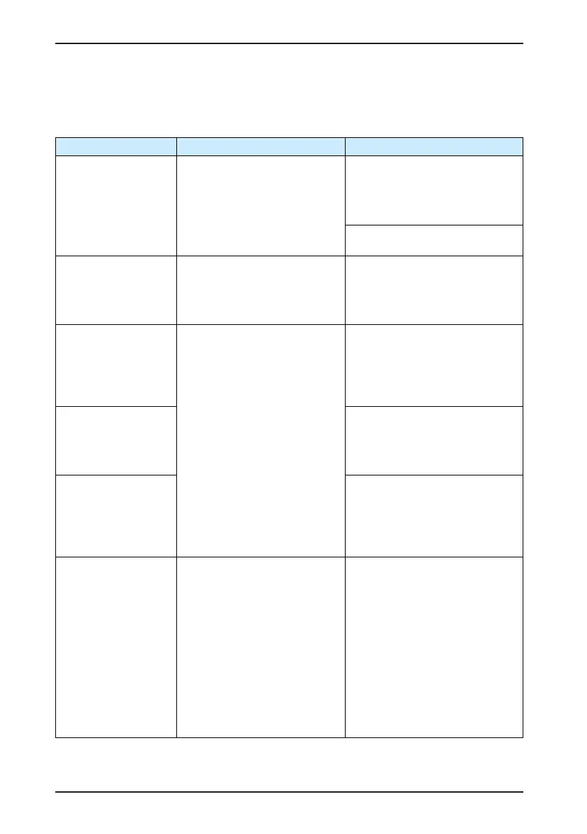
Cause Conrming Method Corrective Action
1. The cable of the
external regen resistor
is in poor connection,
becomes loose or
breaks.
•
Disconnect the external regen
resistor and measure whether
the resistance of the regen
resistor is s ∞.
•
Measure whether the resistance
between P and C is∞.
Replace with a new external regen
resistor and measure its resistance.
If the resistance is consistent
with the nominal value, connect it
between P and C.
Select a normal cable and connect it
between P and C.
2. The jumper across
terminals P and D is
shorted or disconnected
when the internal regen
resistor is used.
•
Measure whether the resistance
between P and D.
Select a normal cable and connect it
between P and D.
3. The setting of H02-
25 is incorrect when the
external regen resistor
is used.
•
View the setting value of H02-
25.
•
Measure the resistance of
the external regen resistor
connected between P and C.
Check whether the resistance
is too large by comparing it with
the regen resistor specication
table in section 1.4..
•
Check whether the value of
H02-27 is greater than the
resistance of the external regen
resistor connected between P
and C.
Set H02-25 correctly based on
section 4.2.
H02-25 = 1 (external regen resistor
used, natural cooling)
H02-25 = 2 (external regen resistor
used, forced air cooling)
4. The resistance of the
selected external regen
resistor is too large
when an external regen
resistor is used.
Select a proper regen resistor
according to section 1.4 Regen
Resistor Specications..
5. H02-27 (resistance of
external regen resistor)
is larger than the
resistance of actually
connected external
regen resistor.
Set H02-27 (resistance of external
regen resistor) consistent with the
resistance of the selected external
regen resistor.
6. The input voltage of
the main circuit exceeds
the specication.
•
Check whether the input voltage
of the main circuit on the servo
drive side complies with the
following specication:
220 V drive:
Effective value: 220 to 240 V
Allowed error: -10% to 10%
(198 to 264 V)
380 V drive:
Effective value: 380 to 440 V
Allowed error: -10% to 10%
(342 to 484 V)
Replace the power supply or adjust
the power voltage according to the
specication on the left.

 Loading...
