IS620P User Manual Chapter 4 Running and Commissioning
- 95 -
When there is interference on the AI1 input signal, set the AI1 input lter time (H03-51).
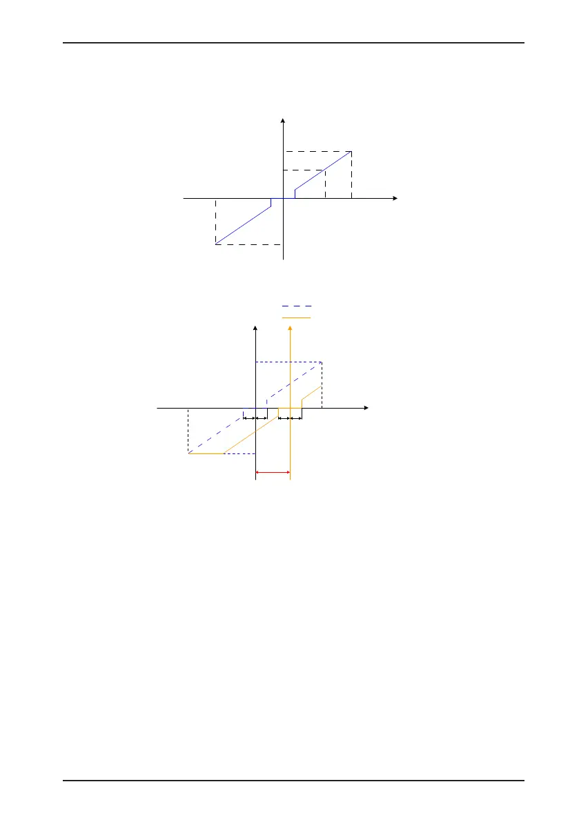
Figure 4-14 No-offset AI1
T_Ref
AI
Torque
Voltage
Torque corresponding
to +10 V (+H03-81)
Torque corresponding
to -10 V (-H03-81)
+10 V
-10 V
Dead zone
(H03-53)
Figure 4-15 After-offset AI2
Voltage
Offset
(H03-50)
Torque corresponding
to -10 V (-H03-81)
Dead zone
(H03-53)
-10V
+10V
Torque corresponding
to +10 V (+H03-81)
Torque
(After-offset)
Torque
(No-offset)
No-offset torque reference curve
After-offset torque reference curve
View the set torque reference (a percentage relative to the rated motor torque) in H03-02.
2. Speed limit in torque control
In the torque control mode, the speed of the servo motor needs to be limited to protect the
mechanism. In the torque control mode, only the output torque reference of the servo motor
is limited, and the speed is not controlled. Therefore, if the set torque reference is larger than
the load torque on the mechanical side, the motor will keep acceleration. This may cause
overload. In this case, the speed limit needs to be set.
When the actual speed exceeds the limit, the difference between the actual speed and the
limit is converted to a certain percentage of torque and cleared negatively, so that the speed
reaches the limited range. The actual speed limit changes with the load. The speed limit can
be set internally or by analog sampling (similar to speed reference in the speed control mode).

 Loading...
