Chapter 3 Wiring of Servo System IS620P User Manual
- 66 -
Z-TEK, model: ZE551A, 0.8-m USN extension cable, chip model: FT232
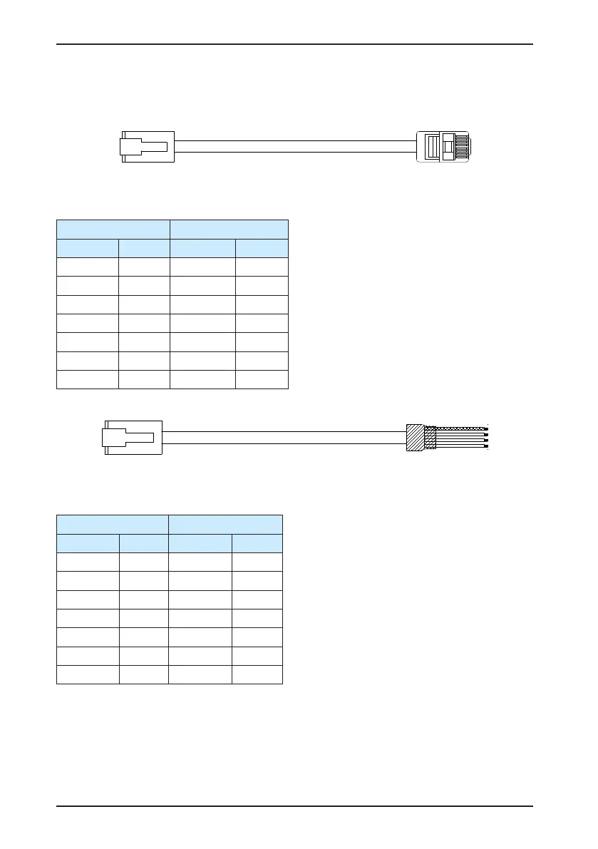
Figure 3-14 Appearance of the communication cable for parallel connection of multiple servo
drives
Table 3-22 Pin denition of the communication cable for parallel connection
A B
Signal Pin No. Signal Pin No.
GND 8 GND 8
CANH 1 CANH 1
CANL 2 CANL 2
CGND 3 CGND 3
RS485+ 4 RS485+ 4
RS485- 5 RS485- 5
PE (shield) Housing PE (shield) Housing
Figure 3-15 Appearance of the communication cable between the PLC and the servo drive
Table 3-23 Pin denition of the communication cable between the PLC and the servo drive
A B
Signal Pin No. Signal Pin No.
GND 8 GND 8
CANH 1 CANH 1
CANL 2 CANL 2
CGND 3 CGND 3
RS485+ 4 RS485+ 4
RS485- 5 RS485- 5
PE (shield) Housing PE (shield) Housing

 Loading...
