Chapter 4 Running and Commissioning IS620P User Manual
- 96 -
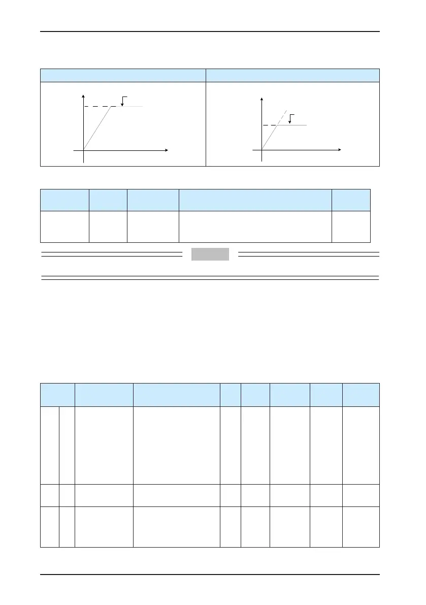
Table 4-6 Speed limit diagram
Without Speed Limit With Speed Limit
Speed
Maximum
speed
Overspeed may cause
mechanical damage.
t
Speed
Speed
limit
The speed
is limited.
t
When the speed is limited, the DO terminal outputs the signal described in the following table.
Function No.
Function
Name
Description Setting Remarks
FunOUT.8 V-LT Speed limit
Conrming speed limit in torque control:
Valid: Motor speed limited
Invalid: Motor speed not limited
-
The V-LT function needs to be allocated to a certain DI.
The speed limit source can be internal or external. When the internal speed limit source is
used (H07-17 = 0), directly set the forward speed limit (H07-19) and reverse speed limit (H07-
20). When H07-17 = 2, the DI allocated with FunIN.36 is used to select H0-19 or H07-20 as
speed limit. When the external speed limit source is used (H07-17 = 1), the analog setting
is specied in H07-18, and the corresponding relationship between the speed limit and the
analog setting is set based on actual requirements. In addition, the externally set speed limit
must be lower than the internally set speed limit to prevent faults due to improper setting of
external speed limit.
The speed limit setting modes are set in the following function codes.
Function
Code
Parameter
Name
Setting Range Unit Default
Effective
Time
Property
Control
Mode
H07 17
Speed limit
source
0: Internal setting (in
torque control)
1: External V-LMT
setting
2: H07-19/H07-20 as
internal speed limit
source selected by
FunIN.36 (V-SEL)
- 0 Immediate
During
running
T
H07 18 V-LMT selection
1: AI1
2: AI2
- 1 Immediate
During
running
T
H07 19
Forward speed
limit/Speed
limit 1 in torque
control
0–6000 rpm 3000 Immediate
During
running
T

 Loading...
