IS620P User Manual Chapter 3 Wiring of Servo System
- 59 -
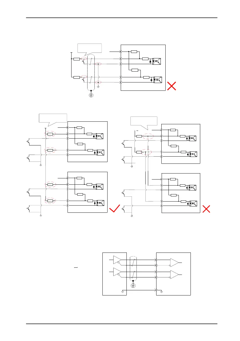
Wrong connection 4: Terminals are not correctly connected, resulting in burnout of terminals.
Servo drive
PULSE+
PULSE-
35
41
43
240 Ω
PULLHI
SIGN+
SIGN-
37
39
240 Ω
2.4 kΩ
2.4 kΩ
COM
R1
R1
VCC
OC signal not
connected to
specified terminal
Wrong connection 5: Multiple terminals share the same current-limit resistor, resulting in that
pulses are inaccurately received.
Servo drive
PULSE+
PULSE-
35
41
43
240 Ω
PULLHI
SIGN+
SIGN-
37
39
240 Ω
2.4 kΩ
2.4 kΩ
COM
R1
R1
VCC
Servo drive
PULSE+
PULSE-
35
41
43
240 Ω
PULLHI
SIGN+
SIGN-
37
39
240 Ω
2.4 kΩ
2.4 kΩ
COM
R1
R1
A
B
Terminals are
connected with current-
limit resistors separately
Servo drive
PULSE+
PULSE-
35
41
43
240 Ω
PULLHI
SIGN+
SIGN-
37
39
240 Ω
2.4 kΩ
2.4 kΩ
COM
R1
R1
VCC
Servo drive
PULSE+
PULSE-
35
41
43
240 Ω
PULLHI
SIGN+
SIGN-
37
39
240 Ω
2.4 kΩ
2.4 kΩ
COM
A
B
Terminals are not
connected with separate
current-limit resistors
■
High-Speed Reference Pulse Input
High-speed reference pulse and symbol signals at the host controller can only be output to the
servo drive via differential drive output.
HSIGN+
HSIGN-
HPULSE+
HPULSE-
38
36
42
Servo drive
29
GND
GND
Host computer
40
High-speed pulse reference
Min. pulse width: 0.125 us
Max. input frequency: 4 Mpps

 Loading...
