Chapter 3 Wiring of Servo System IS620P User Manual
- 52 -
3.3.1 DI/DO Signals
Table 3-12 DI/DO signal description
Signal
Default
Function
Pin No. Function Description
Common
DI1 P-OT 9 Forward drive forbidden
DI2 N-OT 10 Reverse drive forbidden
DI3 INHIBIT 34 Pulse input forbidden
DI4 ALM-RST 8 Alarm reset (edge valid)
DI5 S-ON 33 Servo enabled
DI6 ZCLAMP 32 Zero clamp function
DI7 GAIN-SEL 31 Gain switchover
DI8
Home
Switch
30 Home switch
DI9 Reserved 12 -
+24V 17 Internal 24 V power supply, voltage
range: 20 to 28 V maximum output
current: 200 mA
COM- 14
COM+ 11 Power supply input (12 to 24 V)
DO1+ S-RDY+ 7
ON when the servo drive is ready
and the S-ON signal can be received.
DO1- S-RDY- 6
DO2+ COIN+ 5
Position reached
DO2- COIN- 4
DO3+ ZERO+ 3
Zero speed
DO3- ZERO- 2
DO4+ ALM+ 1
ON when a fault occurs.
DO4- ALM- 26
DO5+
Home
Attain+
28
ON at home return is completed.
DO5-
Home
Attain-
27
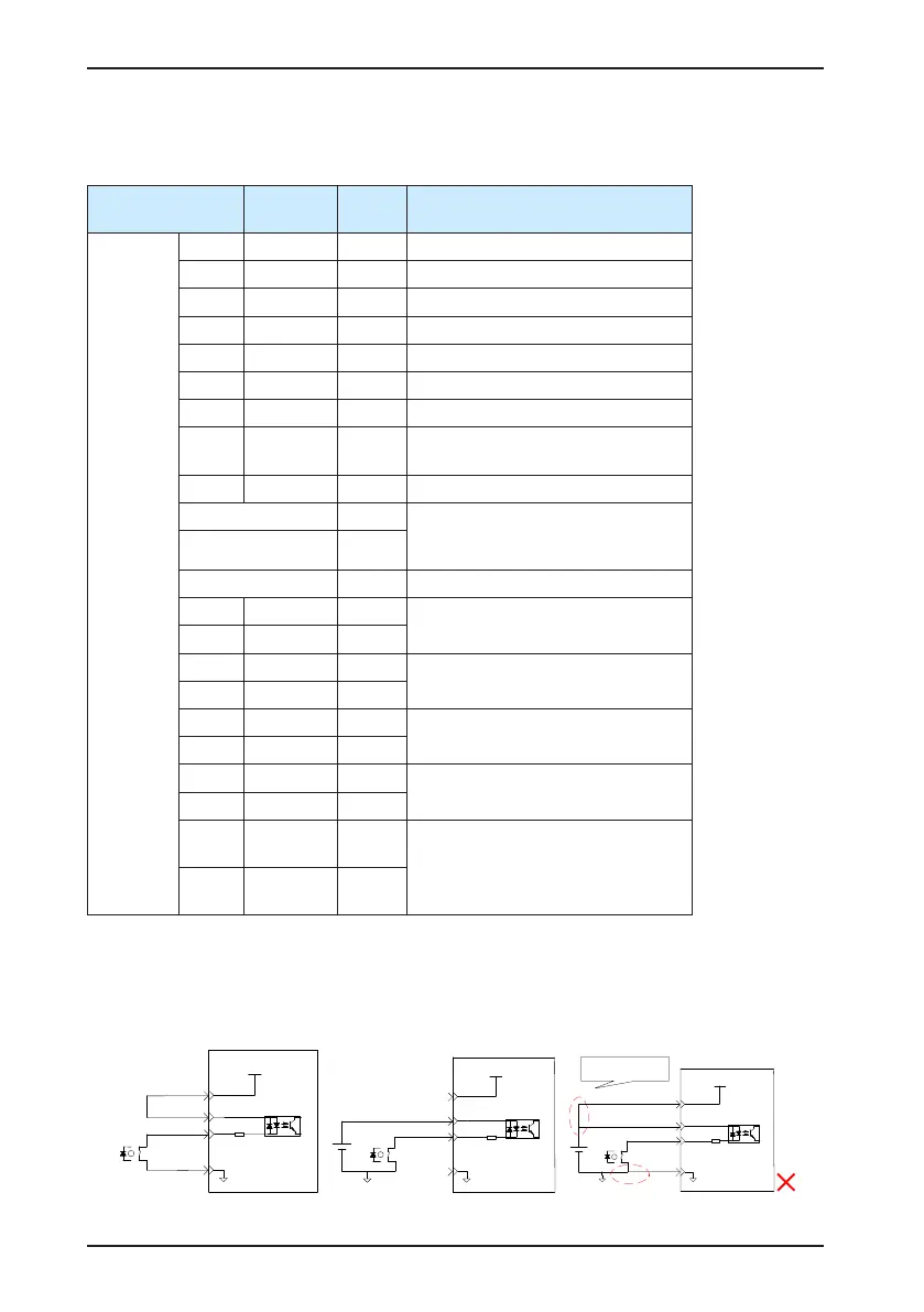
1) DI circuit
DI1 to DI9 circuits are the same. The following takes DI1 circuit as an example.
a) When output signal of the upper device is relay output:
Servo drive
14COM-
+24V power
supply
DI1(CMD1)
24V
4.7 kΩ
COM+
9
11
17
Relay
Use 24 V internal
power supply:
Servo drive
14
COM-
+24V power
supply
DI1(CMD1)
24V
4.7 kΩ
COM+
9
11
17
Relay
Use 24 V external
power supply:
24 VDC
Servo drive
14
COM-
+24V power supply
DI1(CMD1)
24V
4.7 kΩ
COM+
9
11
17
24 VDC
Not using single-
phase power supply

 Loading...
