IS620P User Manual Chapter 3 Wiring of Servo System
- 55 -
3.3.3 Position Reference Input Signals
Table 3-14 Position reference signal description
Signal Pin No. Function Description
Position
reference
PULSE+
PULSE-
SIGN+
SIGN-
41
43
37
39
Common reference pulse
input mode:
•
Differential drive mode
•
OC mode
Pulse input status:
Direction + pulse
Phase A + B quadrature pulse
CW/CCW pulse
HPULSE+
HPULSE-
38
36
High-speed reference pulse input
HSIGN+
HSIGN-
42
40
High-speed position reference symbols
PULLHI 35 External power input terminal of reference pulse
GND 29 Ground
An output circuit for the reference pulse or symbol signal at the host controller can either be
differential drive output or OC output. The following table lists the maximum input frequency
and minimum pulse width of these output modes.
Table 3-15 Correspondence between maximum input frequency and minimum pulse width
Pulse Mode
Max. Frequency
(pps)
Min. Pulse Width
(us)
Common
Differential 500 k 1
OC 200 k 2.5
High-speed differential 4 M 0.125
If the output pulse width of the host controller is smaller than the minimum value, the servo drive will
receive wrong pulses.
■
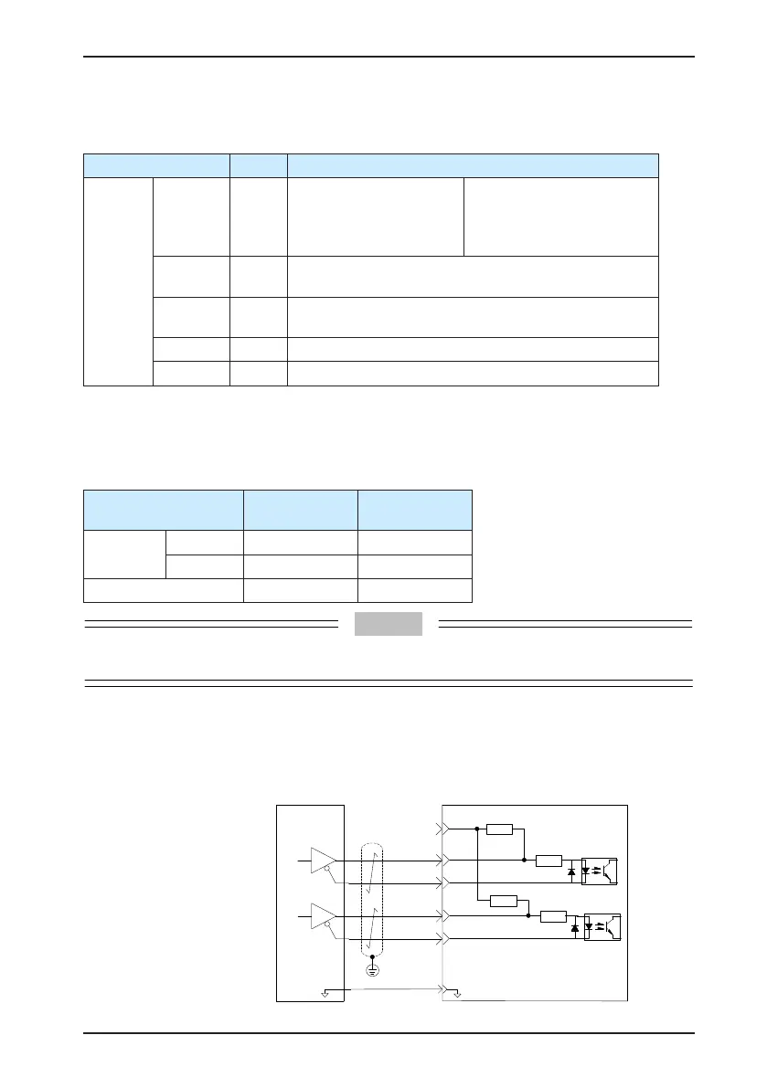
Common Reference Pulse Input
The following gures show the two modes of common reference pulse input.
a) Differential drive mode
Servo drive
PULSE-
SIGN-
35
41
43
240 Ω
37
39
240 Ω
2.4 kΩ
2.4 kΩ
PULSE+
SIGN+
29
GND
GND
Host computer
Common pulse
position reference:
Min. pulse width: 1 us
Max. input frequency:
500 kpps

 Loading...
