IS620P User Manual Chapter 3 Wiring of Servo System
- 39 -
3.1 Servo Drive Main Circuit Wiring
3.1.1 Introduction to the Main Circuit
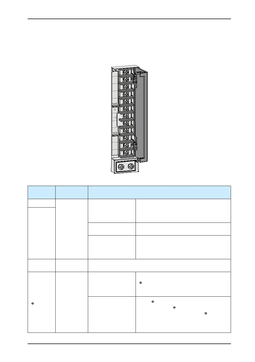
Figure 3-2 Servo drive main circuit wiring example
Table 3-1 Names and functions of main circuit terminals
Terminal
Symbol
Terminal
Name
Terminal Function
L1, L2
Main circuit
power input
terminals
IS620P: S1R6, S2R8,
S5R5
Main circuit single-phase 220 V power input.
Only L1 and L2 terminals are used. Connect
220 VAC power supply between L1 and L2
terminals.
R, S, T
IS620P: S5R5, S7R6,
S012
Main circuit three-phase 220 V power input.
IS620P: T3R5, T5R4,
T8R4,
T012, T017, T021,
T026
Main circuit three-phase 380 V power input.
L1C, L2C
Control power
input terminals
Connect to control power input. For specic value, refer to the rated
voltage on the nameplate.
, D, C
External
regen resistor
terminals
IS620P: S1R6, S2R8
Connect an external regen resistor between
and C if the braking capacity is insufcient.
You need to purchase the external regen
resistor.
IS620P: S5R5, S7R6,
S012, T3R5, T5R4,
T8R4, T012, T017,
T021, T026
Short
and D by default. Remove the
jumper between
and D, and connect an
external regen resistor between
and C if
the braking capacity is insufcient.
You need to purchase the external regen
resistor.

 Loading...
