Chapter 4 Running and Commissioning IS620P User Manual
- 84 -
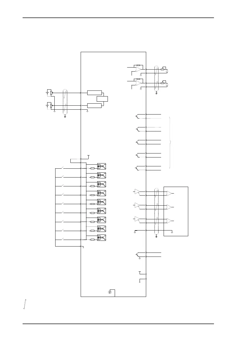
4.2.1 Wiring of the Speed Control Mode
Figure 4-6 Wiring of the speed control mode
Servo drive
The shield of the PE is connected
to the housing of the connector.
Bi-directional
1 mA meter
Bi-directional
1
mA meter
GND
AO1
GND
AO2
A
AI1
20
AI2
18
GND
19
Low-pass filter
A/D
converter
Low-pass filter
A
PAO-
PAO+
21
22
PBO-
PBO+
25
23
PZO-
PZO+
13
24
Phase Z output
Phase A output
29
GND
GND
PZ-OUT
GND
44
29
Encoder phase Z
open-collector output
GND
COIN+(DO2+)
5
4 COIN-(DO2-)
S-RDY+(DO1+)
7
6
S-RDY-(DO1-)
ZERO+(DO3+)
3
2
ZERO-(DO3-)
ALM+(DO4+)
1
26
ALM
-(DO
4-)
HomeAttain+(DO5+)
28
27
HomeAttain-(DO5-)
State output
29
15
GND
+5V
GND
5V
P-OT(DI1)
24V
COM+
9
11
17
+24 V
power
supply
N-OT(DI2)
10
INHIBIT(DI3)
34
ALM-RST(DI4)
8
S-ON(DI5)
33
ZCLAMP(DI6)
32
GAIN-SEL(DI7)
31
HomeSwitch(DI8)
30
Not defined (DI9)
12
COM-
14
4.7 kΩ
4.
7 kΩ
4.7 kΩ
4.7 kΩ
4.7 kΩ
4.7 kΩ
4.7 kΩ
4.7 kΩ
4.7 kΩ
Forward overtravel switch
Reverse overtravel switch
Alarm reset signal
Servo drive enabled
Zero clamp enabled
Gain switchover
Home switch
Not defined
Analog torque limit
Signal input: ±10 V
Impedance: about 9
kΩ
Analog speed
Signal input: ±10 V
Impedance: about 9 kΩ
Pulse forbidden
Analog output: -10 to 10 V
Maximum output: < 1 mA
Analog output: -10 to 10 V
Maximum output: < 1 mA
Phase B output
Encoder frequency-
division pulse
differential output
indicates the twisted pair.

 Loading...
