Chapter 3 Wiring of Servo System IS620P User Manual
- 46 -
9. Conduct maintenance after conrming that the CHARGE indicator is OFF.
10. Do not frequently turn ON and OFF the power supply. Do not turn power ON or OFF more
than once per minute. Since the servo drive contains a capacitor in the power supply,
and high charging current ows for 0.2 seconds when the power supply is turned OFF.
Frequently turning ON and OFF the power supply will deteriorate performance of the main
circuit components inside the servo drive.
11. Use a grounding wire with the same cross-sectional area of the main circuit wire. If the
cross-sectional area of the main circuit wire is less than 1.6 mm
2
, use a grounding wire
with a cross-sectional area of 2.0 mm
2
.
12. The servo drive must be reliably grounded.
13. Do not power on the servo drive when any screw of the terminal block becomes loose or
any cable is loose. Otherwise, a re may occur.
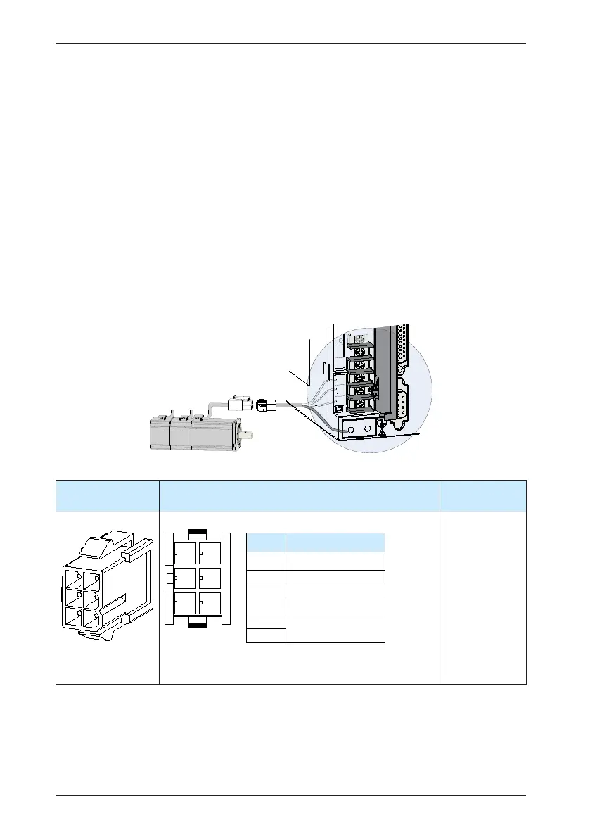
3.1.4 Connecting Servo Drive Output and Servo Motor
Figure 3-6 Example of connecting servo drive output and servo motor
Table 3-7 Connectors of power cables on servo motor side
Connector
Appearance
Terminal Pin Layout
Frame Size of
Adaptable Motor
6-pin black connector
Recommendation:
Plastic housing: MOLEX-50361736
Terminal: MOLEX-39000061
40 (Z series)
60 (Z series)
80 (Z series)
Pin No. Signal
1 U
2 V
4 W
5 PE
3
Brake (regardless of
positive or negative)
6

 Loading...
